Page 30
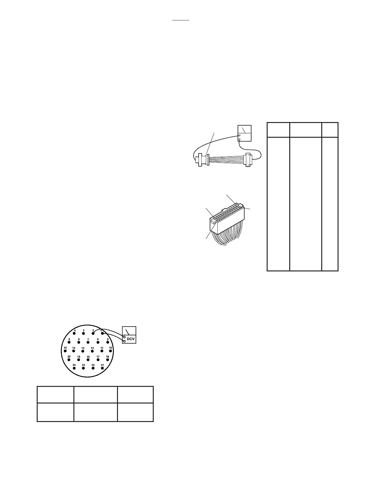
Figure 5-5. Base Connector Continuity Test
5-4. Relay Box
The 120 volt power supply is directly connected to
the relay contacts. When these contacts are
closed, 120 volts is supplied to the solenoids which
are mounted on the hydraulic mini-valves. One
relay is used to supply 120V to the pump/motor and
is always activated no matter what control function
is selected. The brake locking circuit relay is also
activated when any control function other than
BRAKE UNLOCK is
initially
selected.
Also, inside the relay box is a step-down trans-
former and full-wave rectifier which decreases the
line voltage to 5.5 volts. This low voltage potential
controls the relays by the use of the hand-held
pendant control buttons. Basically the relays en-
able a 5.5 volt potential to control the 120 volt circuit.
The following tests will determine if the relay box is
functioning correctly.
b. Test Results:
If you do not receive continuity between any of the
pins, either the micro-switch in the Pendant Control
is defective or a wire is broken. Either of these
problems can be repaired easily.
If you receive correct readings with the meter, the
Pendant Control is okay.
c. Wiring Harness Test
The following test checks the wires leading from
the relay box connector CN8 to the 24 pin connec-
tor table socket. These wires apply low voltage to
the pendant control buttons.
1. The power cord should be plugged into the
wall socket and the main switch turned ON.
2. Disconnect the pendant control from the
base connector. All other connectors should be
connected.
3. Use a DC voltmeter 10V scale and measure
the following pins located in the 24 pin table base
connector. See figure 5-4.
NOTE
Pin 19 in table base connector will have
no voltage potential unless 1 of the
return-to-level micro-switches are acti-
vated, i.e. trendelenburg, tilt, etc.
d. Test Results:
If you do not receive the correct voltage reading,
the wiring or connector pins may be faulty. Discon-
nect connector CN8 from the relay box and using
an ohmmeter, test the continuity between the cor-
responding pins in connectors CN8 and the table
base connector. See figure 5-5. If the correct
readings are obtained, this part of the circuit is
okay.
Figure 5-4. Table Base Connector
+ TEST - TEST DC
LEAD LEAD VOLTS
1 2, 3, 21, 22 0
1 4 - 20, 23, 24 5 - 6
BASE
CONN. COLOR CN8
1 Red/White A1
2 White B1
3 Black A2
4RedB2
5 White/Red A3
6 Yellow B3
7 Brown A4
8 White/Brown B4
9 Blue/Whte A5
10 Orange B5
11 White/Orange A6
12 Gray B6
13 White/Gray A7
14 White/Yellow B7
15 Purple/White A8
16 Black/White B8
17 Purple A9
18 White/Purple B9
19 Blue/Yellow A10
20 Blue/Red B10
21 A11
22 B11
23 Blue A12
24 White/Blue B12
A13
B13
OHM
BASE
CONNECTOR
A13
B13
A1
B1
CN8
CN8
3500

 Loading...


