Page 60
7-1. Relay Box Adjustments
The Relay Box contains variable resistors for ad-
justing the operating timers for the BRAKE SET
and BRAKE UNLOCK functions. The Relay Box
for the battery model tables also has variable
resistors for setting the Power Off timer and the
battery recharge warning circuit. These timers are
set at the factory and usually never need adjust-
ment. If an adjustment is necessary, remove the
relay box cover and use the following procedures.
See figures 7-1 and 7-2.
SECTION VII ELECTRICAL SYSTEM ADJUSTMENTS
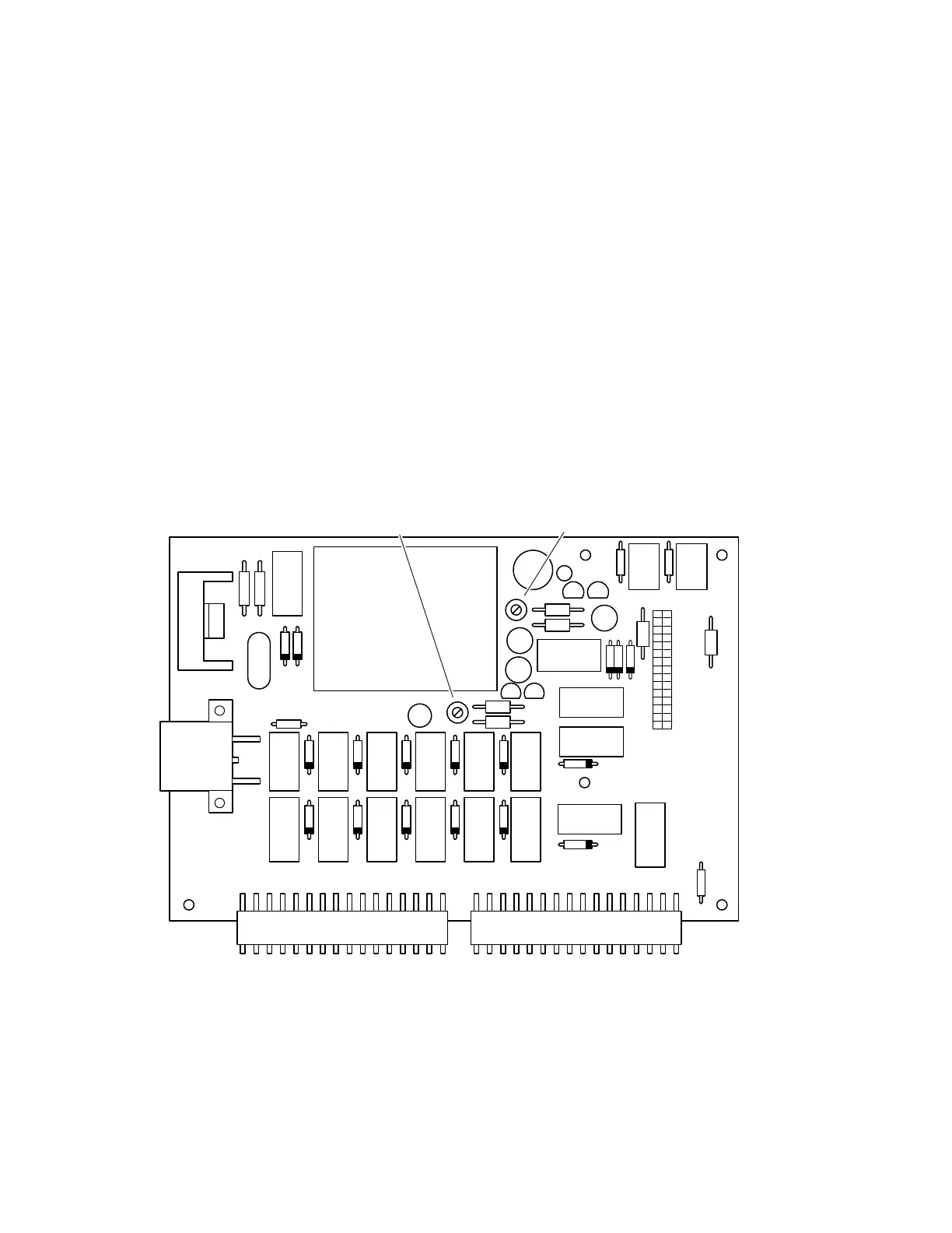
a. Brake Release Timer
The Brake Release Timer is set for about 7 sec-
onds and is controlled by the variable resistor VR1
on the relay box circuit board. Turn the adjuster
clockwise to increase the operating time. Counter-
clockwise to decrease the operating time.
b. Brake Set Timer
The Brake Set Timer is set for about 7 seconds and
is controlled by the variable resistor VR2 on the
relay box circuit board. Turn the adjuster clock-
wise to increase the operating time. Counterclock-
wise to decrease the operating time.
Figure 7-1. Relay Box Adjustments Model 3500
VR-2
VR-1

 Loading...


