Page 52
NOTE
If the pump has been activated continu-
ously for 1-1/2 to 2 minutes, the thermal
protector will interrupt the power to the
pump.
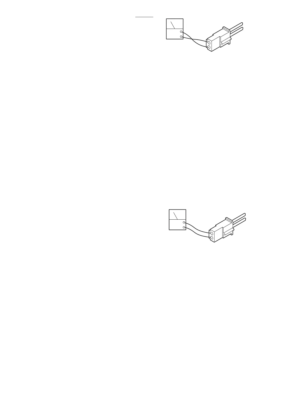
b. Thermal Protector Test
The Thermal Protector is built in to the pump motor
and is used to interrupt the current flow to the pump
motor to protect it from possible damage due to
overheating.
1. Turn OFF both BATTERY and AC120V
operating modes.
2. Use an ohmmeter to test for continuity
between terminals 1 and 2 on the connector CN16.
See figure 6-22.
d. Test #2
The solenoid can be checked out using an ohm-
meter R x 1 scale.
1. Measure the resistance between the two
pin connector in question as shown in figure 6-20.
Connector must be disconnected. Polarity of
meter leads is not important.
2. The meter should read approximately 16
ohms at room temperature.
3. Measure the resistance between either pin
and ground.
4. Meter should read infinity.
e. Test Results:
If the solenoid does not check out with the meter,
it is more than likely defective and must be
replaced.
NOTE
Whenever there are several compo-
nents of the same type, a defective
unit can also be detected by substi-
tuting a known good unit or wire con-
nector. In some cases this may be
faster than using a multi-meter.
6-12. Motor/Pump Assembly
The hydraulic pump motor is a 24 volt DC electric
motor. The oil pump unit is attached to the bottom
of the motor and is a gear type displacement
pump with a pumping capacity of .4 liter per min.
The Motor/Pump Assembly is mounted on insula-
tors in the base of the table.
a. Motor/Pump Test
1. Disconnect motor connector CN15. Leave
all other connectors connected and activate either
BATTERY or AC120V operating mode.
2. Activate any function and use a DC voltme-
ter to measure across the two pin connector. Pin
1(+) and pin 2(-). See figure 6-21. Meter should
read 24-28 volts.
Figure 6-21. Motor Input Voltage
Figure 6-22. Thermal Protector
DCV
CN15
2
1
DCV
2
1
CN16
3. The Thermal Relay should reset itself after
approximately one minute.
4. The Thermal Relay should activate after 1-
1/2 to 2 minutes of continuous pump operation.
c. Motor Resistance Test
The motor can be statically checked for resistance
using an ohmmeter. This test is not 100% accurate
because you are checking the motor with very low
voltage from the meter and without any load.
1. Using an ohmmeter R x 1 scale, measure the
resistance between the two pins of CN15. See
figure 6-22.
3500B

 Loading...


