Page 28
SECTION V ELECTRICAL SYSTEM TROUBLESHOOTING
5-1. Troubleshooting Notes
The basic operation of each component will be
defined along with a drawing and explanation on
how to check it out.
Certain defective components could cause the
entire table to stop functioning or only one control
function to stop. It would depend on what part of the
component failed. Other defective components
would only cause one control function to stop.
The following defective components could cause
all control functions to be affected:
a. Motor/Pump Assembly (starting capacitor)
b. Main Switch Circuit and Wiring
The following defective components could cause
all control functions to be affected or only one
control function:
a. Relay Box
b. Pendant Control
The component listed below would only affect one
control function:
Solenoid
When troubleshooting an electrical circuit, start at
the problem and work back to the power source.
5-2. Main Switch
The main power supply, 120 VAC, 60 HZ, comes in
through the power cord and through the main
switch. The main switch opens both lines when in
the "OFF" position. Two 10 amp fuses are used to
protect the complete electrical system and are
located next to the main switch.
a. Main Switch Test
The following test will determine if line voltage is
applied to connector CN4, which in turn would
power the table.
1. Plug the power cord into the 120VAC power
supply (wall receptacle) and turn ON the main
switch.
2. Disconnect connector CN4 from the relay
box. See figure 5-1. Leave all other connectors
connected.
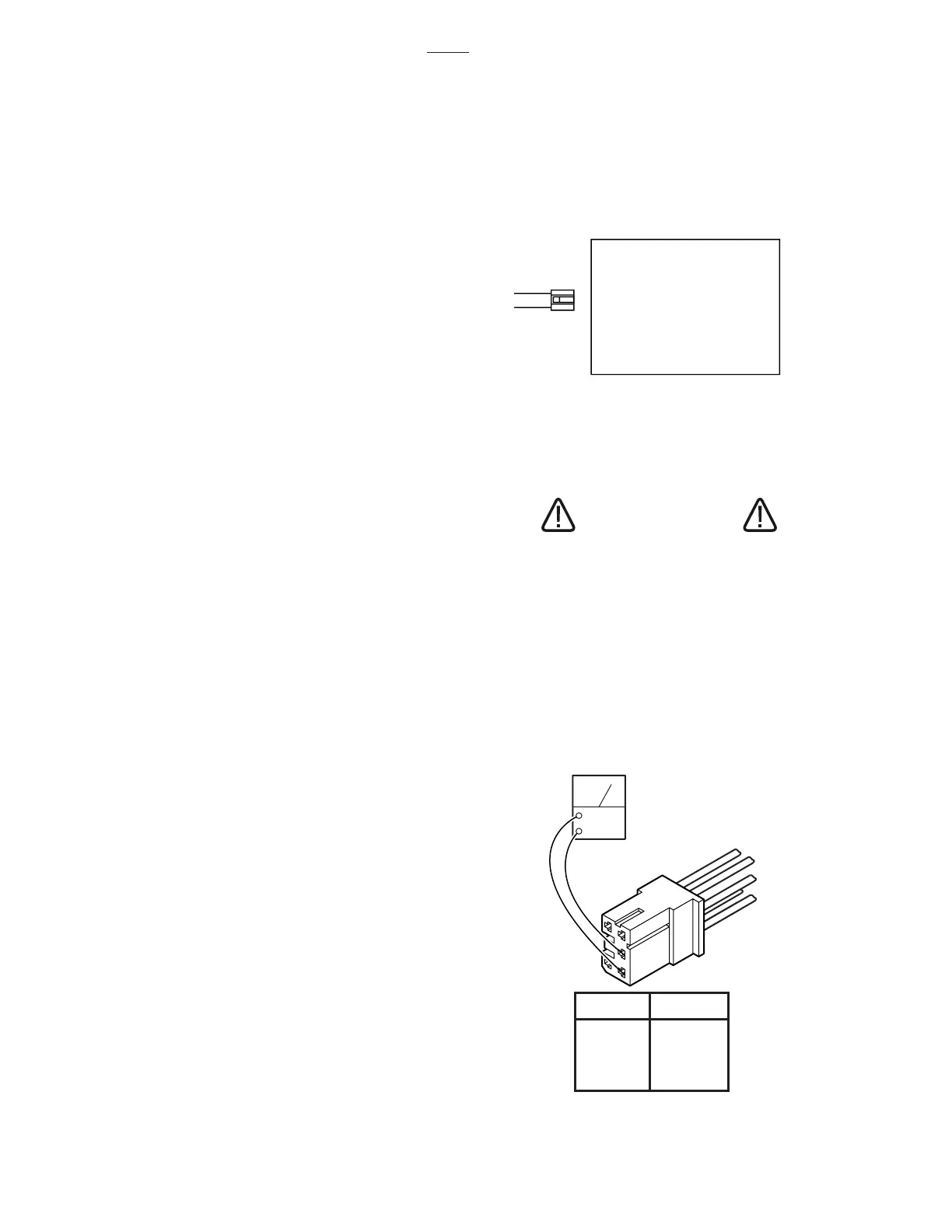
Figure 5-2. Connector CN4
Figure 5-1. Main Power Test
CAUTION
Line voltage (120 VAC) will be mea-
sured in this test. Do not touch uninsu-
lated connector pins or meter test leads.
3. Use an AC voltmeter capable of measuring
120 VAC and measure the voltage between pins
1 and 2 (black and white wires) located in connec-
tor CN4. See figure 5-2. You should receive line
voltage 120 VAC.
3500
CN4
RELAY BOX
PIN NO. COLOR
1 White
2 Black
3Red
4 Blue
5 Yellow
ACV
5
4
1
2
3

 Loading...


