Page 51
ACVOHM
BLUE
WHITE/BLUE
BLUE
WHITE/BLUE
BLUE
CN1
RED
BLUE
WHITE/BLUE
BLUE
WHITE/BLUE
BLUE
WHITE/BLUE
BLUE
WHITE/BLUE
BLUE
WHITE/BLUE
BLUE
WHITE/
BLUE
BLUE
WHITE/
BLUE
BLUE
BLACK/
WHITE
BLUE
WHITE/BLACK
BLUE
WHITE/BLUE
BLUE
WHITE/BLUE
BLUE
WHITE/BLUE
BLUE
WHITE/BLUE
BLUE
WHITE/BLUE
BLUE
WHITE/BLUE
BLUE
WHITE/BLUE
BLUE
WHITE/BLUE
BLUE
WHITE/BLUE
BLUE
BROWN
BLUE
ORANGE
BLUE
BROWN/WHITE
BLUE
WHITE/BROWN
BLUE
WHITE/GREY
BLUE
PURPLE
BLUE
WHITE
BLUE
BLACK
BLUE
WHITE/PURPLE
BLUE
GREY
BLUE
BLUE/WHITE
BLUE
RED/WHITE
BLUE
WHITE/ORANGE
BLUE
YELLOW
BLUE
WHITE/RED
ELEV.
UP
DN.
UP
DN.
UP FT.
DN. HD.
UN
LOCK
LOCK
DN.
UP
HD
DN.
HD
UP.
RT.
LT.
REFX
FLEX
TREND FLEX KIDNEY BRAKE
TABLE
SLIDING
LAT.
TILT
BACK
SECT.
LEG
SECT.
16
15
14
13
12
11
10
9
8
7
6
5
4
3
2
1
CN2A
16
15
14
13
12
11
10
9
8
7
6
5
4
3
2
1
CN2B
4
3
2
1
3500B
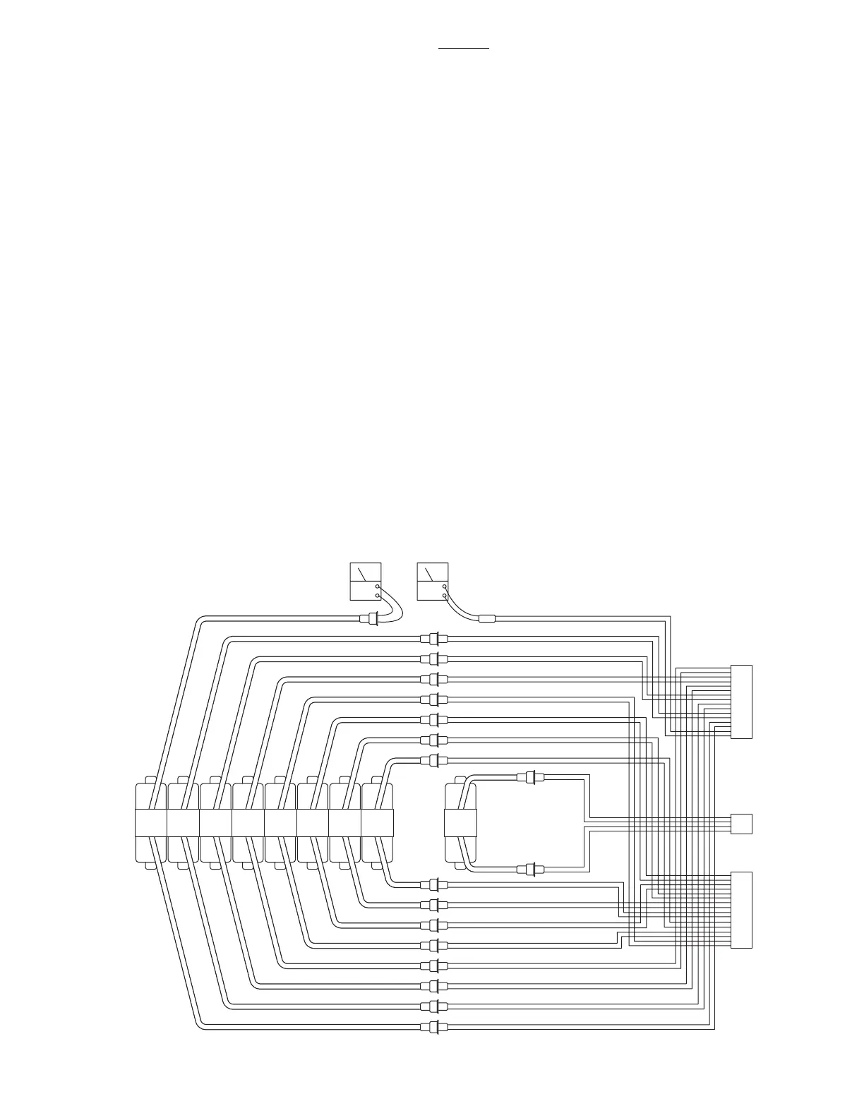
6-11. Solenoids
The solenoids are energized by 24 volt potential
that is controlled by the relay box.
The solenoid windings are protected from exces-
sive heat by an internal thermal fuse that will open
after approx. 7 minutes of continuous operation.
The solenoid must be replaced if the internal ther-
mal fuse has been blown.
The solenoids are mounted directly on either side
of the hydraulic mini-valves and push the spool
valve in one direction or the other depending upon
which solenoid is activated.
a. Solenoid Test
The following tests will check the voltage applied
to the solenoids and the resistance of the solenoid
coil.
b. Test #1
1. Activate either BATTERY or AC120V oper-
ating mode.
2. Disconnect the 2 pin connector from the
solenoid in question, all other connectors should be
connected. See figure 6-20.
3. Use a DC voltmeter and measure the
voltage across the 2 pin connector. Pin 1(+), and
pin 2(-). Meter should read approximately 24-28
volts.
NOTE
•The appropriate pendant control but-
ton must be pushed during this test.
The motor will run when this test is
performed, and the brake locking sole-
noid will be activated by any function
other than MOVE.
•If a solenoid does not function when
the pendant control button is pushed,
the problem could be the pendant con-
trol, the relay box, or the solenoid.
c. Test Results:
If you do not receive the correct voltage, the prob-
lem could be in the wires leading down to the
connector. The problem could also be in the relay
box or the Pendant Control (refer to appropriate
section for troubleshooting).
If the correct voltage is obtained, everything is good
up to that point and the problem is more than likely
the solenoid.
Figure 6-20. Solenoid Test

 Loading...


