Page 50
3500B
e. Test Results:
If you do not receive the correct meter readings, the
relay box is defective and should be replaced.
NOTE
•Before deciding the relay box is de-
fective, check the wires and pins in the
connector blocks to make sure they
are not loose or making a bad connec-
tion with their mate.
•If the battery power is ON and no table
functions have been activated for 3
hours, the power off circuit will interrupt
the battery power.
f. Checking Output to Pendant Control
The output to the Pendant Control can not be tested
without specialized equipment. If all tests have
been conducted and it appears that the Relay Box
is faulty, contact SKYTRON.
NOTE
The Relay Box connectors CN7 (Pen-
dant Control), and CN8 (Auxiliary Base
Connector), are interchangeable.
6-10. Main Wire Harness Continuity Tests
If correct meter readings are not received in tests
between components, before replacing the compo-
nents, test the Main Wire Harness to be sure all
connectors and wires are making a good connec-
tion.
a. CN4 to Batteries Test
1. Disconnect connectors CN4 and the (+) and
(-) connectors from the batteries. Leave all other
connectors connected.
2. Using an ohmmeter, test for continuity
between pin 1 of CN4 and battery (+) connector.
Also test between pin 2 of CN4 and battery (-)
connector. See figure 6-17.
Figure 6-17.
Figure 6-19. CN4, CN14, and CN51
NOTE
The 15 amp battery protection fuse is in
the line between CN4 pin 1 and the
battery connector. Test the continuity
of the fuse if correct meter reading is not
received.
b. CN4 to CN12 Test
1. Disconnect connectors CN4, CN15 and
CN16. Leave all other connectors connected.
2. Using an ohmmeter, test for continuity
between the pins of CN4 and pins on CN15 and
CN16. See figure 6-18.
OHM
7
6
5
CN4
(+)
(-)
1
2
3
4
Figure 6-18.
OHM
7
6
5
1
2
4
2
1
CN15 OR CN16
CN4
CN-4
3
4
7
4
1
2
0
0
0
0
CN-15
1
2
CN-16 OHMS
3
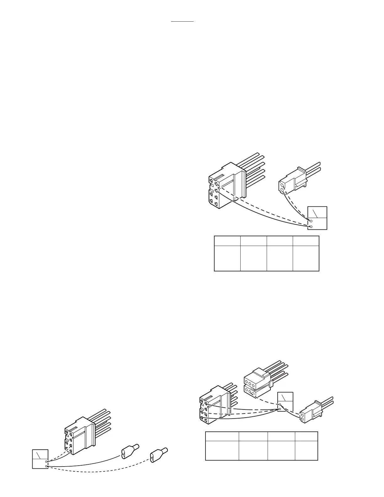
c. CN4 to Charging Box Test
1. Disconnect connectors CN4, CN14 and
CN51. Leave all other connectors connected.
2. Using an ohmmeter, test for continuity
between pins 4, 5 and 6 of CN4, pins 1 and 2 of
CN14, and pin 4 of CN51. See figure 6-19.
OHM
CN14
7
6
5
1
2
3
CN-14
1
2
5
6
4
4
0
0
0
CN-4
CN4
CN-51
CN51
OHMS
5
6
4
2
3
1
4

 Loading...


