Page 49
3500B
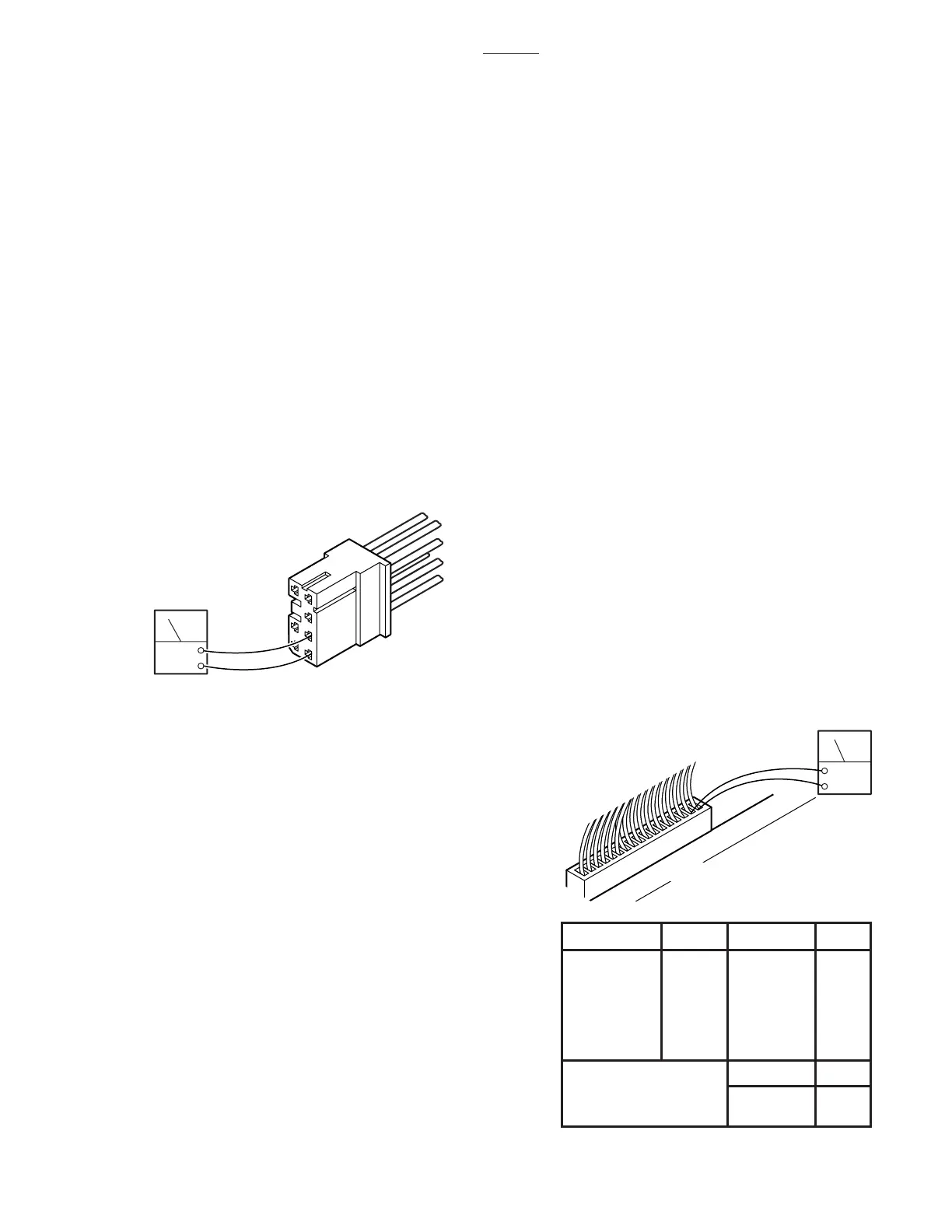
a. Checking Relay Box Input Power
1. Connect power cord to table. Plug the power
cord into the 120VAC supply (wall receptacle).
Disconnect connector CN4, leave all other con-
nectors connected.
2. Using a DC voltmeter, test input power for
both the BATTERY and AC120V operating modes.
See figure 6-15. Meter should read approximately
24 -28 volts.
BATTERY mode AC120V mode
(Main Power OFF) (Main Power ON)
pin1=(+) pin 5=(+)
pin2=(-) pin 6=(-)
Connector CN4 Color Code
Pin 1 Red Pin 5 White
Pin 2 Blue Pin 6 Black
Pin 3 Yellow Pin 7 Yellow
Pin 4 Blue
b. Test Results:
If you do not receive the correct meter readings,
the problem is in the input wiring, connectors or
components. If the correct readings are obtained,
proceed to the next step.
c. Checking Output to Pump
1. Disconnect pump connector CN15, connect
all other connectors and activate the AC120V
operating mode.
2. Test CN15 at pin 1(+) and pin 2(-) with a DC
voltmeter. Meter should read approximately 24-28
volts when any function button is activated. If no
voltage is present, use an ohmmeter to test the
continuity from CN15 to CN4 (yellow and blue
wires). Refer to figure 6-15 for CN4 pin locations.
Figure 6-15. Relay Box Input
Figure 6-16. Solenoid Output Connectors
d. Checking Output to Solenoids
This test checks the voltage that is used to
energize the solenoids.
1. Activate either BATTERY or AC120V oper-
ating mode.
NOTE
•The Brake Lock function is activated
by pressing any function button (except
BRAKE UNLOCK). A timer in the Re-
lay Box allows continuous output for
about 7 seconds. If the brakes are
already locked, no output is provided.
•The BRAKE UNLOCK button activates
another timer in the relay box which
allows continuous output for the brake
release function for approximately 7
seconds. If the brakes are already
released (using the BRAKE UNLOCK
button) no output is provided.
2. Test connectors CN1, CN2A and CN2B
from the back while attached to the relay box. All
connectors should be connected.
3. Activate each of the pendant control buttons
and measure the output voltage for the correspond-
ing connector pins with a DC voltmeter. See figure
6-16.
DCV
7
6
5
1
2
3
4
FUNCTION PINS FUNCTION PINS
Table Up 1 - 2
Leg Up
1 - 2
Table Down 3 - 4
Leg Down
3 - 4
Trend 5 - 6
Kidney Up
5 - 6
Rev Trend 7 - 8
Kidney Down
7 - 8
9 - 10 9 - 10
11 - 12 11 - 12
Tilt Right
13 - 14
Tilt
Reflex
Flex
Left
15 - 16
13 - 14
15 - 16
CN2B
Brake Set
Back Up
Back Down
Slide Foot
Slide Head
1 - 2
Brake Unlock 3 - 4
CN1
CN2A
ACV
CN1, CN2A OR CN2B
16
1

 Loading...


