Page 31
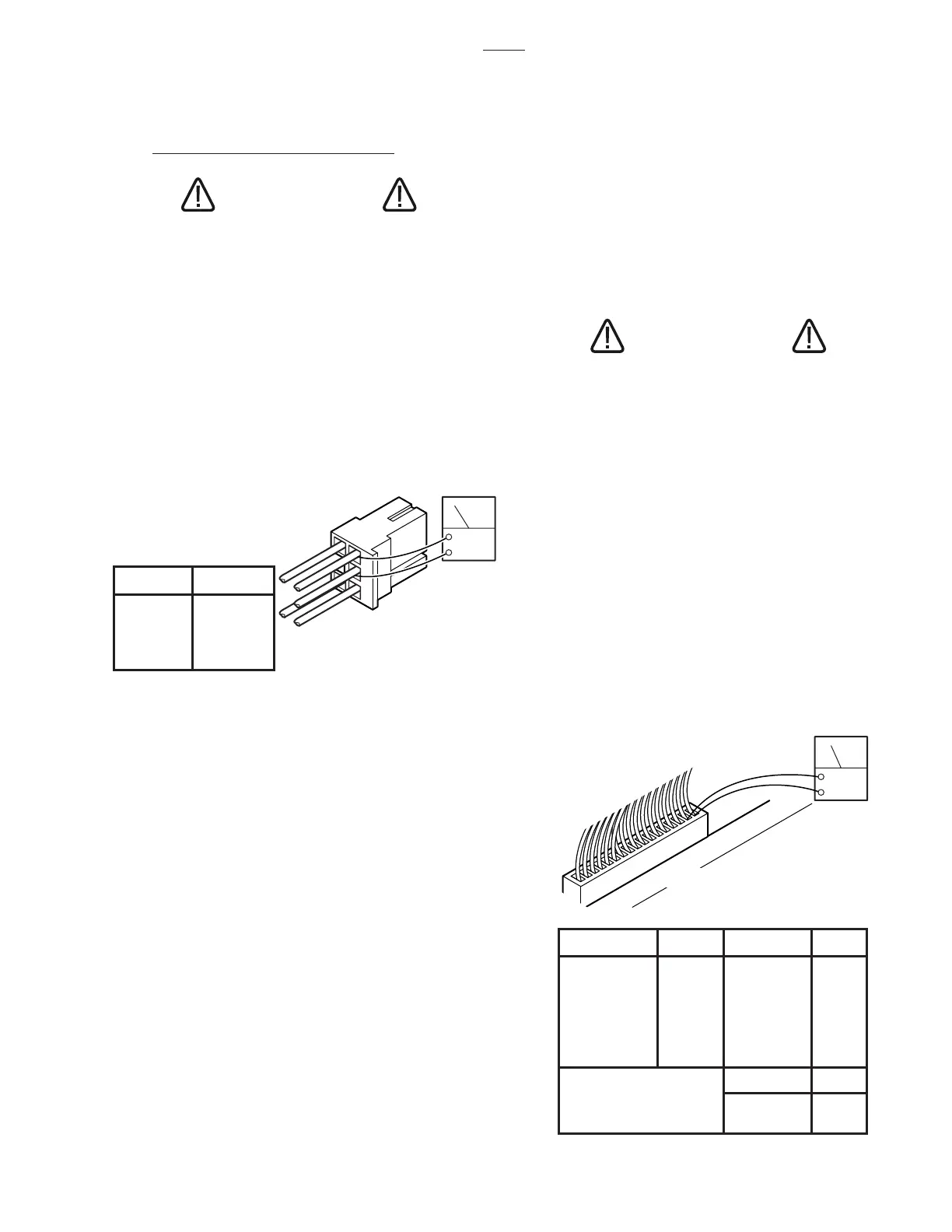
PIN NO. COLOR
1 White
2 Black
3 Red
4 Blue
5 Yellow
3
5
4
1
ACV
2
FUNCTION PINS FUNCTION PINS
Table Up 1 - 2 Leg Up 1 - 2
Table Down 3 - 4 Leg Down 3 - 4
Rev Trend 5 - 6 Kidney Up 5 - 6
Trend 7 - 8 Kidney Down 7 - 8
Back Up 9 - 10 Brake Set 9 - 10
Back Down 11 - 12 Brake Unlock 11 - 12
Tilt Right 13 - 14 Flex 13 - 14
Tilt Left 15 - 16 Reflex 15 - 16
CN7B
Slide Head 1 - 2
Slide Foot 3 - 4
CN6
CN7A
ACV
CN6, CN7A OR CN7B
16
1
a. Relay Box Input Connector CN4
1. Plug the power cord into the 120 VAC power
supply (wall receptacle) and turn the main switch
ON. Leave all connectors connected.
CAUTION
Line voltage (120 VAC) will be mea-
sured in this test. Do not touch uninsu-
lated connector pins or meter test leads.
2. Use an AC voltmeter capable of measuring
120 volts and measure the voltage between pins 1
(white) and 2 (black) of connector CN4 for input
voltage. See figure 5-6. Meter should read line
voltage 120 VAC.
3. Activate any table function with the Pendant
Control and using an AC voltmeter, test the voltage
at pins 3 and 4 of CN4 for output to the pump. Meter
should read 120 VAC.
d. Test Results:
If you do not receive the correct meter readings, the
relay box or wiring is defective. If the correct
readings are obtained, this part of the relay box is
okay. Proceed to the next step.
e. Relay Box Output Connectors CN6, CN7A
& CN7B
This test checks the high voltage (120V) that is
used to energize the solenoids.
CAUTION
120 VAC will be measured in this test.
Do not touch uninsulated connector
pins or meter test leads.
1. The power cord should be plugged into the
wall receptacle and main switch turned ON.
2. Disconnect the motor connector CN15. All
other connectors should be connected. Test con-
nectors CN6, CN7A and CN7B from the back while
attached to the relay box.
3. Activate each of the Pendant Control buttons
and using an AC voltmeter capable of measuring
120VAC, measure the voltage between the appro-
priate connector pins located in connector CN6,
CN7A or CN7B. See figure 5-7. Polarity of meter
test leads is not important. Meter should read
120VAC.
Figure 5-6. Connector CN4
b. Test Results:
If you do not receive the correct meter readings, the
relay box or wiring is defective. If the correct
readings are obtained, this part of the relay box is
okay. Proceed to the next step.
c. Relay Box Output Connector CN8
This test checks the low voltage applied to the pen-
dant control buttons.
1. The power cord should be plugged into the
wall receptacle and main switch turned ON.
2. Disconnect Pendant Control connector. All
other connectors should be connected.
3. Using a DC voltmeter, measure the voltage
between pin 1(+) and pins 4 through 24 (-) of the
table base connector. See figure 5-4. Meter should
read 5-6 volts.
Figure 5-7. Relay Box Output Connectors
CN6 and CN7
3500

 Loading...


