Page 45
b. Test Results
If the correct voltage is obtained, everything is
good up to this point and the problem would have
to be in another area.
If you do not receive the correct measurements,
the problem may be in the wires, connectors, or
transformer. The transformer is located in the rear
of the base under the stainless steel base cover.
The stainless steel cover will have to be discon-
nected and lifted from the base for access to the
transformer for further testing.
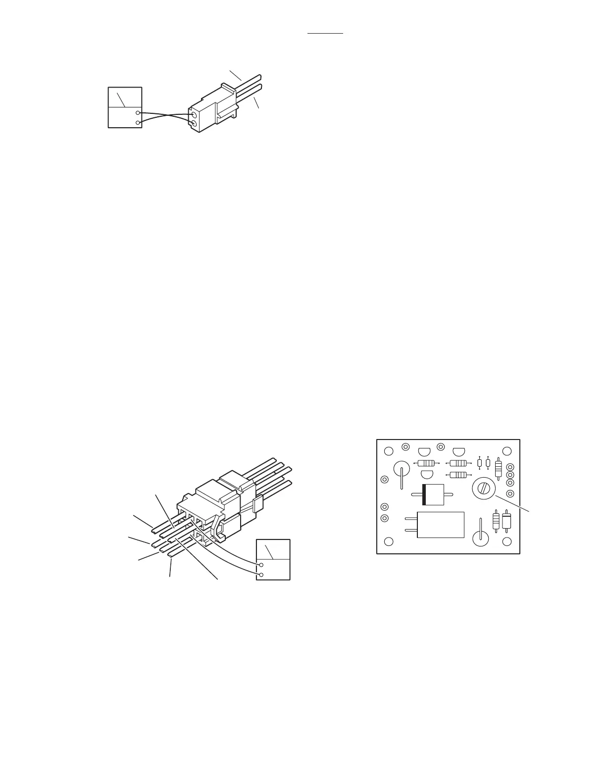
c. Battery Charging Box Test
1. Make sure all connectors are connected and
turn AC120V operation ON. Using a DC voltmeter,
test pin 3(+) and pin 4(-) of CN51. DO NOT
disconnect connector CN51. See figure 6-6.
4. Meter should read 26.5 ±1VDC if charger is
operating. If batteries are fully charged there will be
under 5 volts at pins 5 and 6.
d. Test Results
If you do not receive the correct readings, the
charger system, connectors, wires, or the trans-
former may be defective.
e. Charging System Output Adjustment
If output reading at pins 3 and 4 is not 26.5 ± 1VDC,
the output can be adjusted at the variable resistor
VR51 on the circuit board inside the Charging Box.
See figure 6-7. Turn the adjuster clockwise to
decrease the voltage. Counterclockwise to in-
crease the voltage.
NOTE
The battery connectors must be dis-
connected to adjust the battery charger
output.
3500B
Figure 6-5. Connector CN13 Test
ACV
BROWN
(2)
RED
(1)
2. Meter should read 26.5 ±1VDC.
3. Test pin 5(+) and pin 6(-) of CN51 with DC
voltmeter to test operation of CHARGING indicator
light (next to power cord connector).
Figure 6-6. Connector CN51
DCV
CN51
5
3
1
RED
(3)
(5) RED / WHITE
(6) BLUE / WHITE
BLACK
(4)
(2) BROWN
(1) BROWN
Figure 6-7
VR51

 Loading...


