Page 34
a. Motor/Pump Test
The following tests will check the voltage applied to
the motor and the resistance of the motor field
windings.
CAUTION
Line voltage will be measured in this
test. Do not touch uninsulated connec-
tor pins or meter test leads.
b. Step #1
1. Plug the power cord into 120 VAC power
supply (wall receptacle). Turn main switch ON.
2. Disconnect the 3 pin connector CN15 at the
motor. Leave all other connectors connected. See
figure 5-9.
c. Test Results:
If you do not receive the correct meter readings, the
problem could be in the wires, connectors, relay
box, or main switch (refer to appropriate section for
troubleshooting).
If the correct voltage is obtained, everything is good
up to that point and the problem could be either the
motor or the starting capacitor.
d. Step #2
If the starting capacitor is shorted or grounded, the
motor will not run. Capacitors very seldom fail, and
it requires a dielectric tester to accurately test one.
However, an ohmmeter can be used to determine
if the capacitor will store a low voltage charge and
most of the time this is adequate.
1. Turn the main switch OFF.
2. Connector CN15 should be disconnected.
3. Use the R x 100 scale of the ohmmeter and
touch pins 2 and 3 of connector CN15. See figure
5-10.
e. Test Results:
The meter needle should move up scale and then
back down to infinity. This would indicate that the
capacitor is storing an electrical charge.
NOTE
The capacitor may have to be dis-
charged first (by shorting pins 2 and 3
together) before you will be able to see
the ohmmeter needle swing up the scale.
f. Step #3
The motor windings can be statically checked for
resistance using an ohmmeter.
1. Turn main power switch OFF.
2. Connector CN15 should be disconnected.
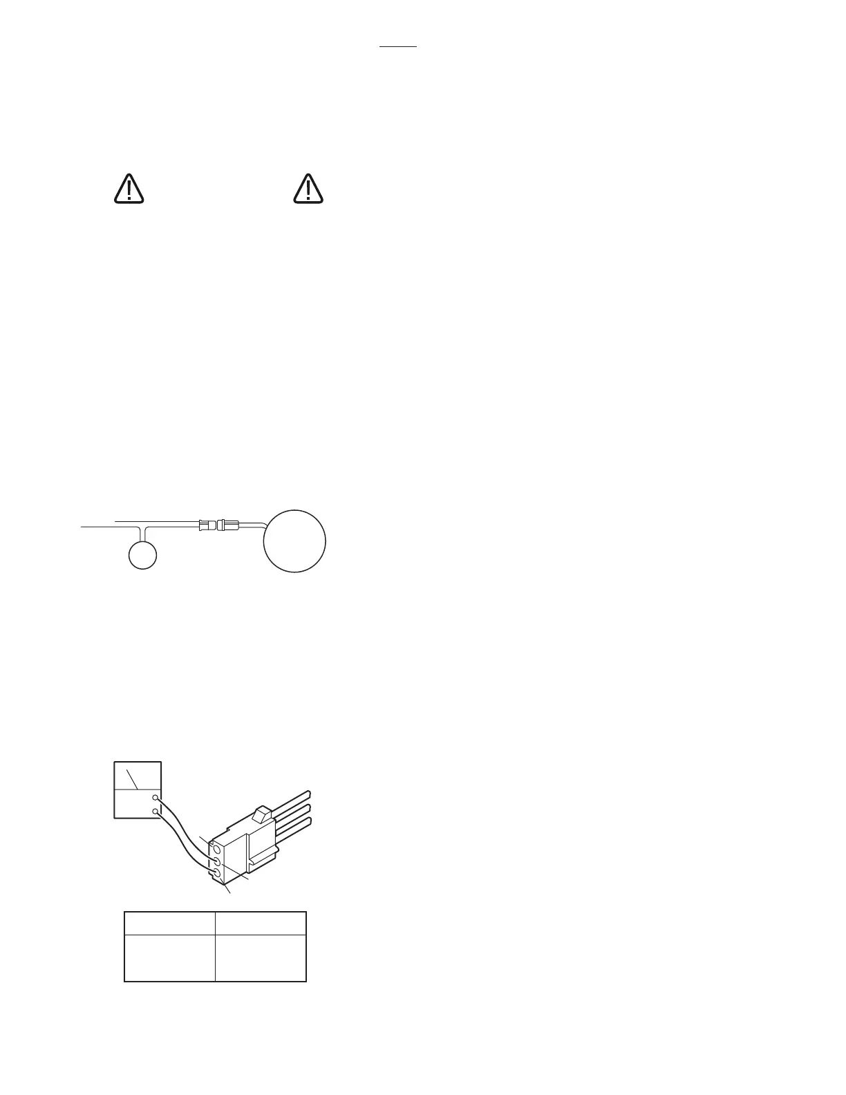
Figure 5-9.
3. Use a voltmeter capable of measuring 120
VAC and measure the following connector pins in
connector CN15. See figure 5-10.
Figure 5-10. Connector CN15
PUMP/MOTOR
ASSEMBLY
CN15
CAPACITOR
ACV
3
2
1
PIN NO
1 - 2
1 - 3
2 - 3
120
120
0
AC VOLTS
3500

 Loading...


