-21-
No.EX※※-OMZ0016
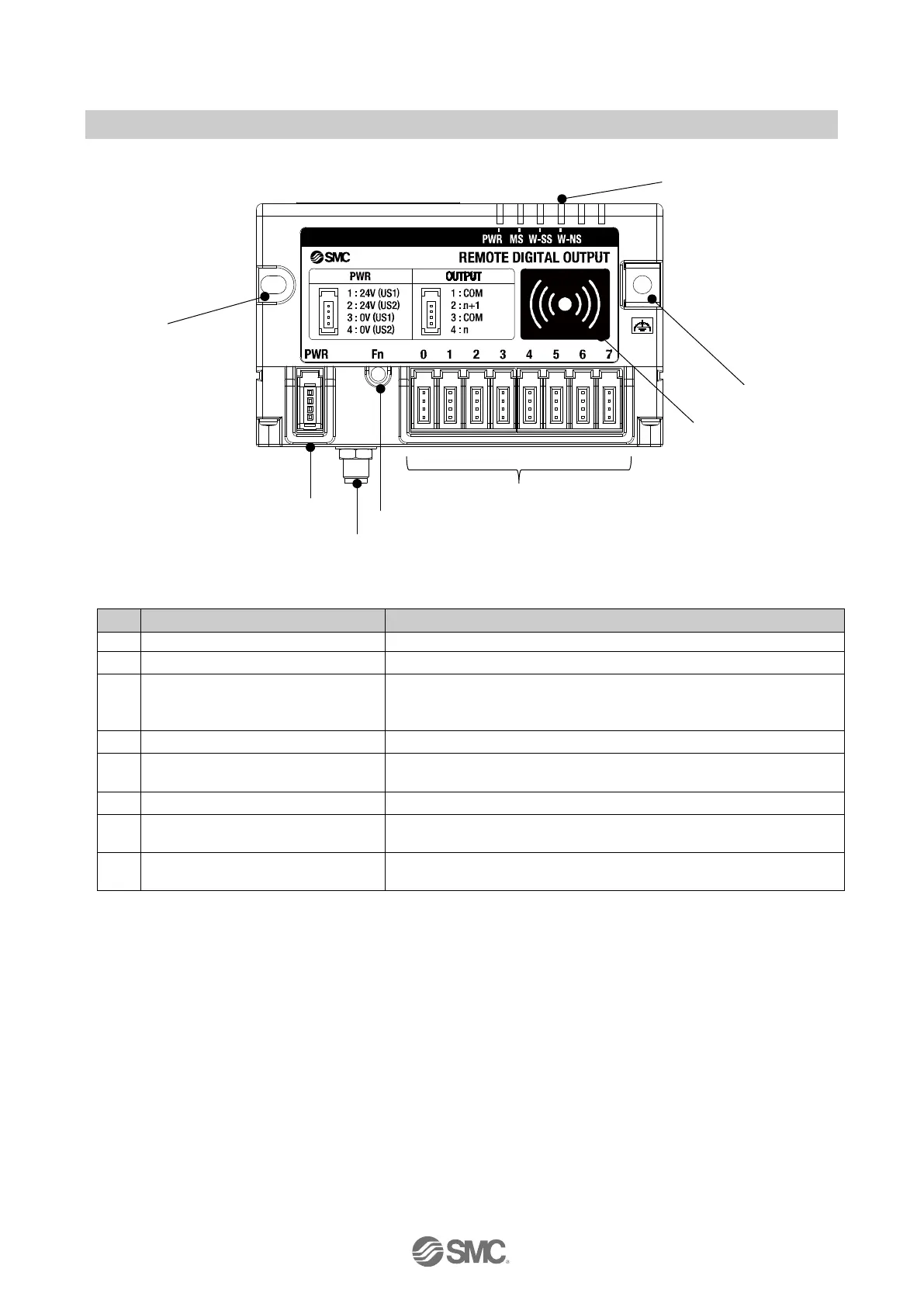
EXW1-RDY*B*
Screw hole for mounting (M4)
Mounting the compact wireless Remote.
2 PWR (Power connector) Supplies power to the compact wireless Remote.
3
RF (SMA coaxial connector)
* Exclusive to external antenna
Connector for the coaxial cable of an external antenna.
Press the button when switching to pairing mode.
5 NFC antenna approach area
This area is in close contact with the NFC reader / writer.
"○" is the center of the NFC antenna.
Indicates the status of the compact wireless Remote.
7
FE terminal, screw hole for
mounting (M4)
To be connected to Ground (for improved noise immunity).
This doubles as a screw hole for mounting
8
Connector for an output device
x 8
Connector for an output device. (PIN2, PIN4: output)
①
⑤
②
③
④
⑥
⑦
⑧
 Loading...