-17-
No.EX※※-OMZ0016
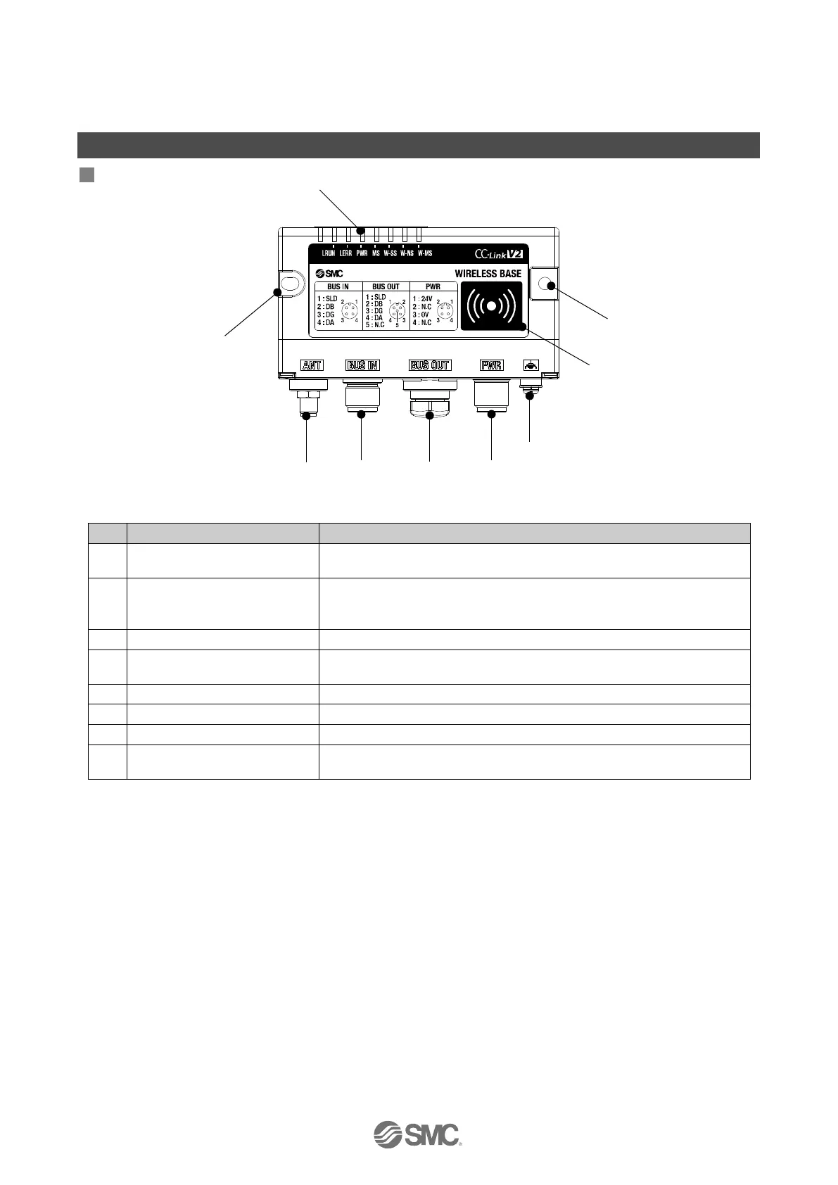
Summary of Product parts
EXW1-BMJA*
Appearance
1
Screw hole for mounting
(2 x M4)
Mounting the compact wireless Base.
2
RF (SMA coaxial connector)
* Exclusive to external
Connector for the coaxial cable of an external antenna.
Connector for a CC-Link communication device.
4 BUS OUT connector
Connector for an additional CC-Link communication device.
* Or it is connected with a terminal resistor.
Supplies power to the compact wireless Base.
To be connected to Ground (for improved noise immunity).
Indicates the status of the compact wireless Base or Remote.
8
NFC antenna approach
area
This area is in close contact with the NFC reader / writer.
"○" is the center of the NFC antenna.
* Grounding should be as close as possible to the product and the grounding wire should be as short as
possible.
 Loading...