HRX-OM-Q026
Chapter 3 Transport and Setting Up
HRSH Series 3.3 Installation
3-19
3.3.4 Contact input/output communicatin wiring
The product has a contact input/output communication function as shown
below. Connect cables referring to the applicable chapter for each function.
(For details of the functions, refer to Operation Manual Communication
Function.)
● Run/Stop input・Remote signal input (Refer to “3.3.5 Wiring of run/stop
signal input and remote signal input”)
● External switch signal input (Refer to “3.3.6 Wiring of external switch
signal input”)
● Output of contact output signal (Refer to “3.3.7 Wiring of contact output
signal Wiring of contact output signal”)
Use the signal cable described below for wiring of each function.
◼ Signal cable
Use the cable and terminals as shown below for wiring of each function.
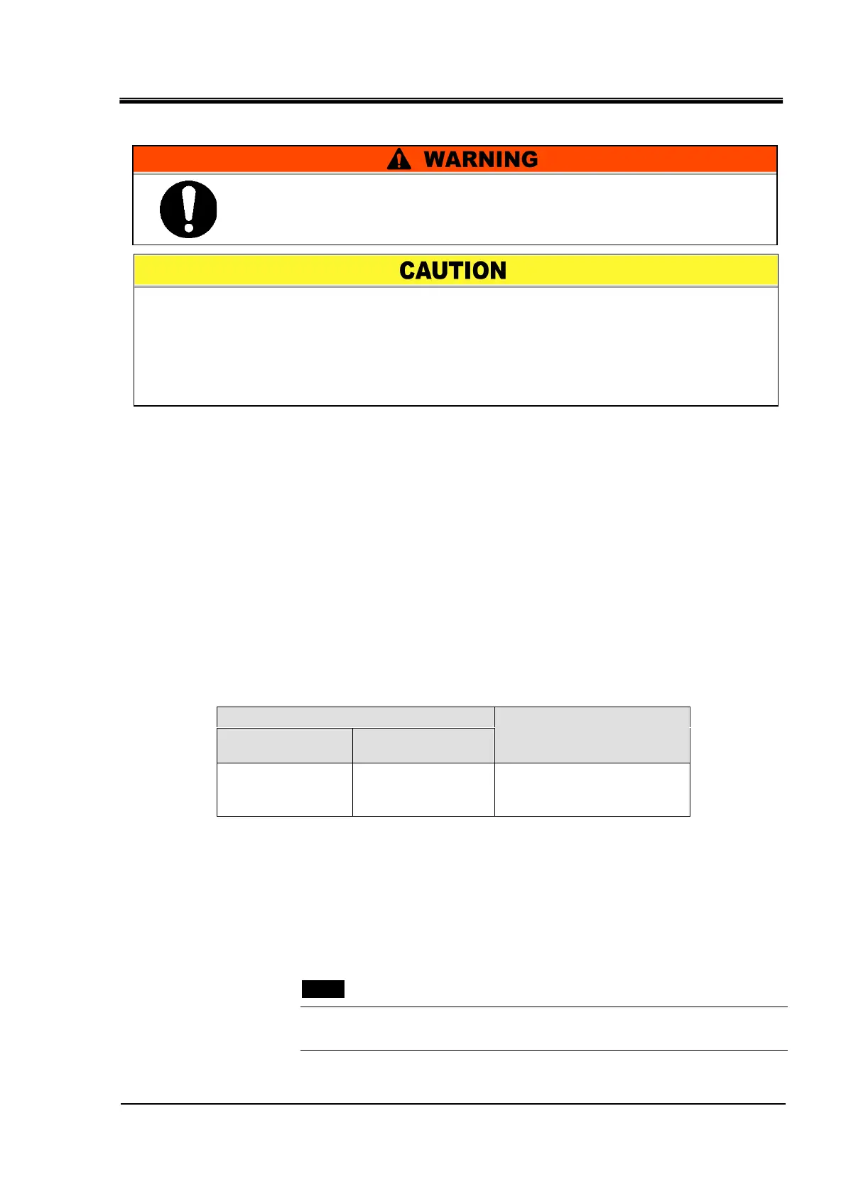
Table 3-5 Signal cable
Terminal block
screw diameter
Recommended
crimp terminal
Y style crimp
terminal
1.25Y-3
0.75 mm
2
(AWG18)
Shielded cable
3.3.5 Wiring of run/stop signal input and remote signal input
Run/Stop signal input and remote signal input enable the product to
operate/stop or switched DIO REMOTE and DIO LOCAL remotely by
applying a contact signal input. This chapter illustrates examples of wiring.
Select DIO mode as the communication mode to activate the run/stop signal
input and remote signal input after wiring referring to Operation Manual
Communication Function.
[Tips]
This product has two input signals. These can be customized depending on
the customer’s application.
Be sure to lock out and tag out the breaker of the facility power
supply (the user’s machine power supply) before wiring.
Use the cable and terminal that are specified.
The capacity of the output contact of the product is limited. If the capacity is not
large enough, install a relay, etc. (to allow for larger capacity). Also, ensure that the
input current of the relay is small enough in relation to the contact capacity of the

 Loading...


