HRX-OM-Q026
Chapter 5 Display and Setting of Various Functions
HRSH Series 5.23 Communication Function
5-73
5.23 Communication Function
5.23.1 Communication function
Contact input/output and serial communication can be performed.
Refer to the Operation Manual Communication Function for more details.
5.23.2 Setting/checking of communication function
The table below shows the set items of the communication function and
default settings.
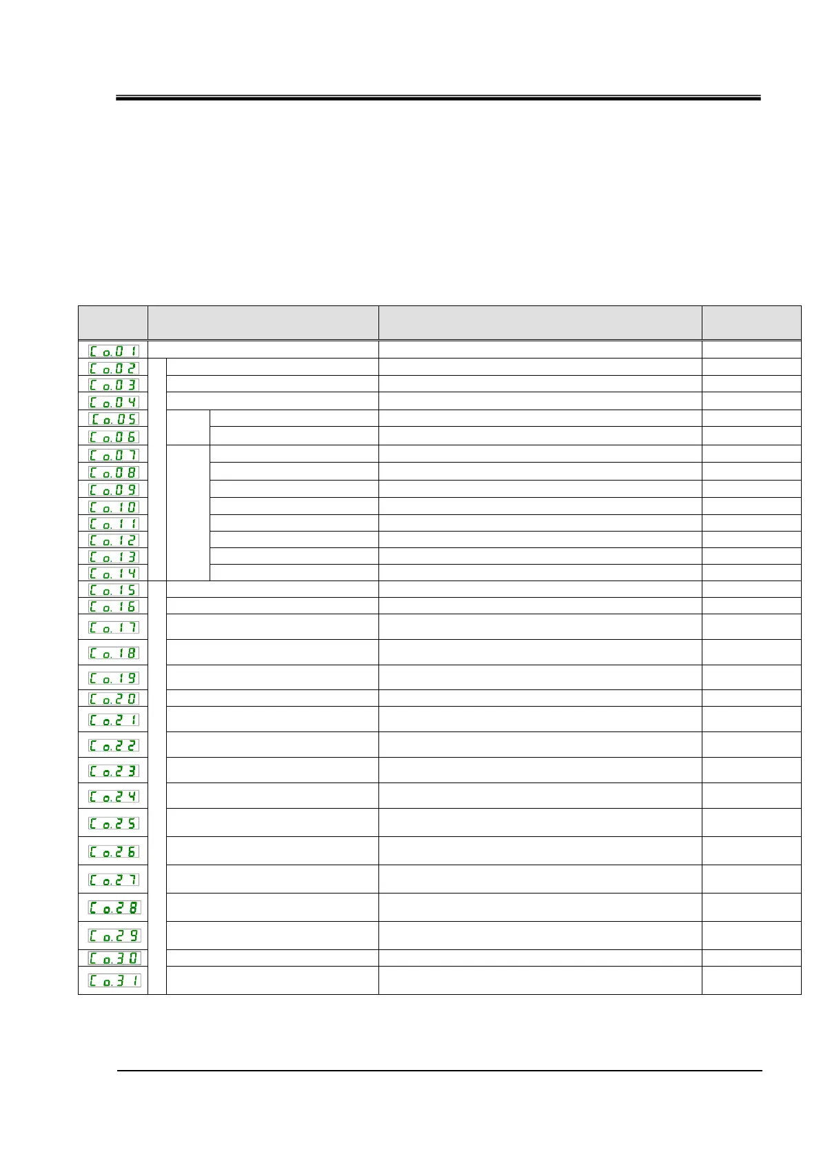
Table 5.23-1 Set items of communication function
Serial communication protocol
Sets serial communication protocol.
Communication specification
Sets serial communication standard.
Sets the terminal unit for RS-485.
Sets communication speed.
Simple
communication
protocol
Sets communication speed.
Sets error detection code.
Sets time delay before sending a response message.
Sets communication range.
Contact
input/output communication
Sets contact input signal 1.
Contact input signal 1 type
Sets input type of the contact input signal 1.
Contact input signal 1 delay timer for
reading
Sets the contact input signal 1 delay timer for reading.
Contact input signal 1 OFF detection
timer
Sets the OFF detection timer of the contact input signal
1.
Sets contact input signal 2.
Contact input signal 2 type
Sets the input type of the contact input signal 2.
Contact input signal 2 delay timer for
reading
Sets the contact input signal 2 delay timer for reading.
Contact input signal 2 OFF detection
timer
Sets the OFF detection timer of the contact input signal
2.
Contact output signal 1 function
Sets the output signal function of the contact output
signal 1.
Contact output signal 1 operation
Sets the output signal operation of the contact output
signal 1.
Contact output signal 1 selected
alarm
Sets the selected alarm for the contact output signal 1.
Contact output signal 2 function
Sets the output signal function of the contact output
signal 2.
Contact output signal 2 operation
Sets the output signal operation of the contact output
signal 2.
Contact output signal 2 selected
alarm
Sets the alarm selected for the contact output signal 2.
Contact output signal 3 function
Sets the output signal function of the contact output
signal 3.
Contact output signal 3 operation
Sets the output signal operation of the contact output 3.
Contact output signal 3 selected
alarm
Sets the alarm selected for the contact output signal 3.
1: Default when CO02 is set to PRO1 or PRO2. 4: Default when CO23 is set to A.SEL.
2: Default when CO15 is set to SW-A or SW-B. 5: Default when CO26 is set to A.SEL.
3: Default when CO19 is set to SW-A or SW-B. 6: Default when CO29 is set to A.SEL.

 Loading...


