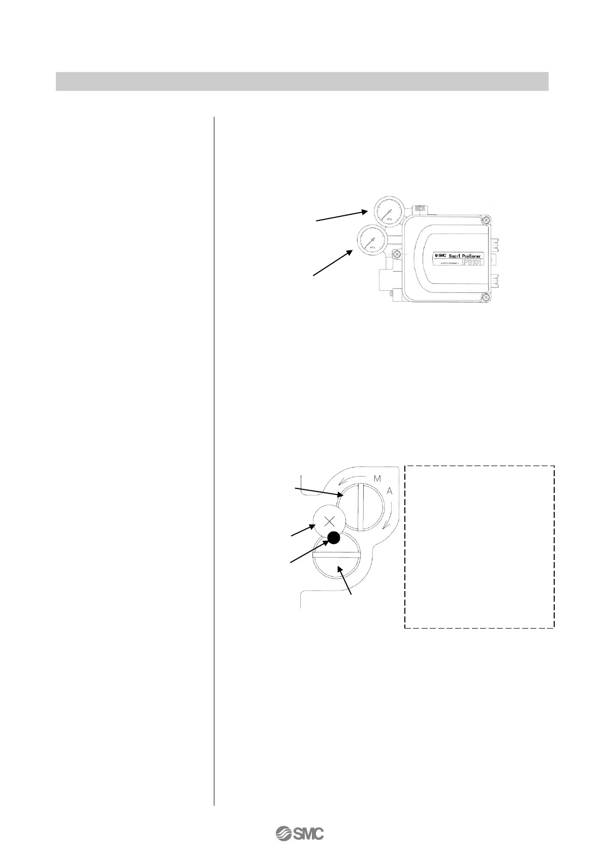
Auto/manual
switch screw
(Built-in fixed orifice)
Stopper screw
(Do not move)
Looseness
prevention
marking
Sensitivity holding screw
(Do not move)
- Be sure to normally tighten
the screw to the auto side
(A) when the positioner is
operated with an input
current.
- Rotation to the manual side
(M) conducts supply
pressure to the OUT1
output. A supply pressure
regulator can adjust the
diaphragm valve and single
acting actuator manual
stroke.
6: Auto and manual mode can be switched by rotating the pilot valve
unit auto/manual switch screw to the manual (M) side as shown in
Fig. 18. A small stopper screw in the top is to prevent loosening and
must not be tampered with or loosened. Also, a sensitivity holding
screw is set prior to factory shipment and must not be accidentally
rotated.
4: The positioner standard stroke is a rotational angle of 60 to 100
o
.
Actuators with a rotating angle of less than 60
o
or over 100
o
are not
available.
5: A Description of pressure gauges mounted on the positioner are as
shown in Fig. 17.

 Loading...