3. Simple balance
current adjustment
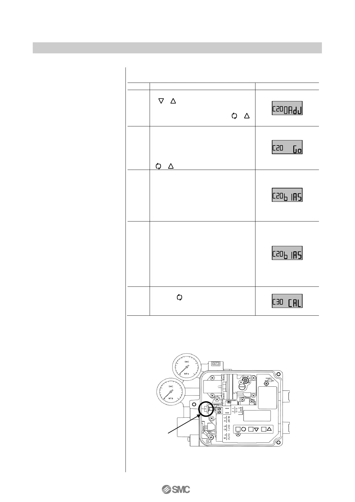
Adjust the torque motor balance current simply.
Press the Down or Up button
( ) in calibration mode to
select zero adjust (0AdJ), and then
hold down the set button ( )
for 1sec. or longer.
The LCD displays go (Go) for
confirmation. Confirm there are no
hazardous conditions due to
starting the actuator, and then
press and hold down the set button
( ) for 1sec. or longer.
The LCD displays bias (biAS).
Check the pressure gauge reading
at the OUT1 port, and if it is any
value other than 0MPa, rotate the
balance adjusting screw
counterclockwise until the reading
reaches 0MPa
*
7
.
Rotate the adjusting screw
clockwise gradually checking the
pressure gauge reading of the
OUT1 port. When the exhaust
sound changes and OUT1 pressure
begins to increase, stop rotating the
balance adjusting screw at the
position before OUT1 pressure
reaches the supply pressure.
Press and hold down the mode
button ( ) for 1sec. or longer to
return to the calibration (CAL) mode
selection screen.
7: For the balance adjusting screw position, refer to Fig. 19.
Adjustments must be made with a flat blade driver. Counterclockwise
rotation decreases pressure and clockwise rotation increases
pressure.

 Loading...