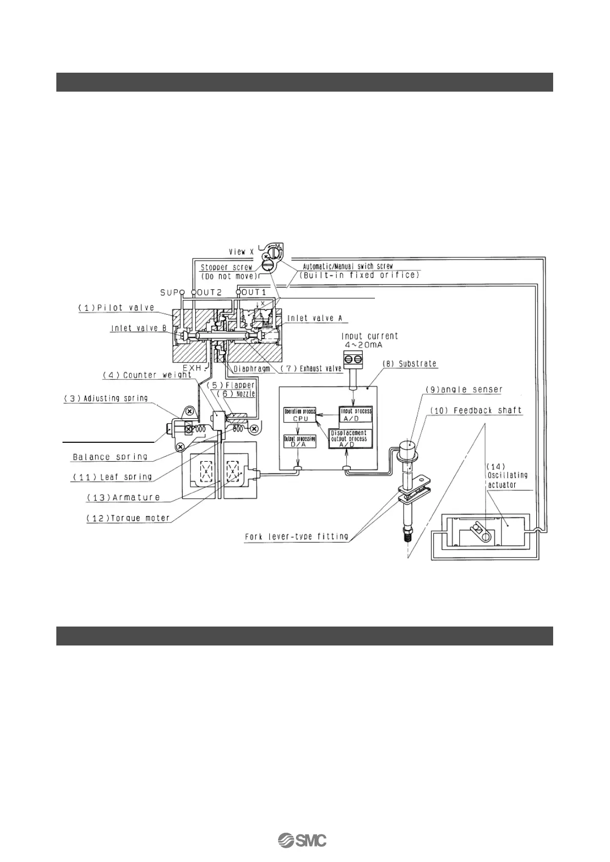
Operating Principle
When the input current (4 to 20mADC) increases, the current which is applied to the coil of the
torque motor (12) through the input, operation and output processing circuits (8) changes, causing
the armature (13) to start rotating with the fulcrum of the leaf spring (11). Along with this, a gap is
created between nozzle (6) and flapper (5), and nozzle back pressure decreases.
As a result, the exhaust valve (7) inside of pilot valve (1) moves to the right, pressure at OUT1
increases and pressure at OUT 2 decreases, causing actuator (14) to move. The motion of actuator
(14) is transmitted through the fork lever-type fitting, feedback shaft (10) and angle sensor (9). The
displacement processing output circuit (8) then matches the input current to the corresponding
output position.
Fig. 3
How to Operation
IP8101 positioner can be operated by two methods, by the operation button (mode, up, down)
installed in the positioner and HART communication (option). Refer to this operation manual for the
operation with operation button and refer to “HART communication function” in the operation
manual separately for the HART communication.

 Loading...