Electrical Wiring
1. Be sure to perform electrical wiring with the input current turned off.
2. Be sure to use a ground terminal and perform electrical construction following relevant
local regulations.
3. Do not touch around the actuator axis when applying an input current after electrical wiring.
4. Use an input current source (4 to 20mA DC) with a secure 12V DC or greater voltage as
close as possible to the input current terminal to avoid voltage drops.
5. Please see “■ATEX Intrinsic Safety Type of Explosion Protected Construction
(52-IP8101-0 4- -M).
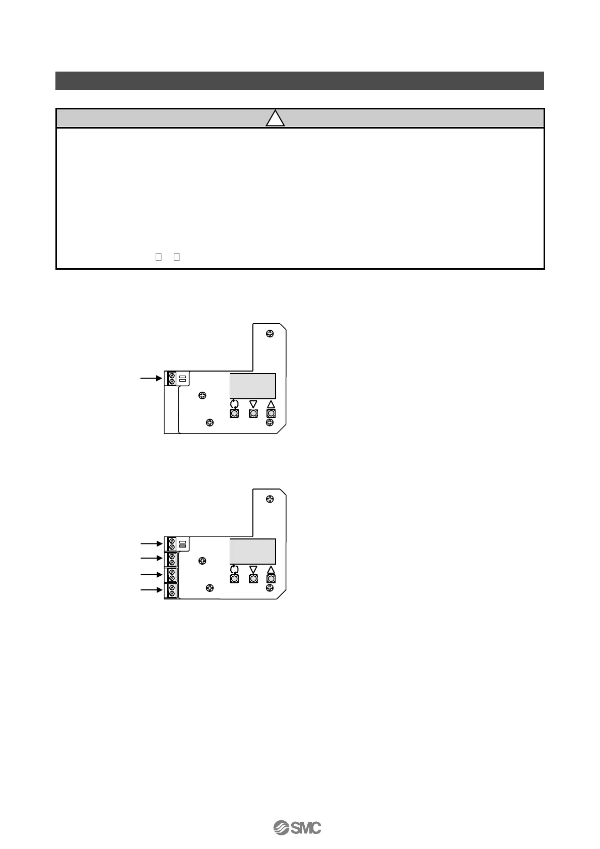
■Without Output Function (IP8101-030 and IP8101-033)
(1) Remove the positioner body cover.
(2) Connect the input current wiring from an
adjusting meter (controller) following Fig. 9
*
1
.
■With Output Function (IP8101-032 and 52-IP8101-034)
(1) Remove the positioner body cover.
(2) Connect input current wiring from an adjusting
meter (controller) and each output wiring
following Fig 10
*
1
.
1: For the wiring details, refer to “■Electrical Wiring”.

 Loading...