Scale Plate Adjustment
(1) Attention should be taken not to have finger caught between the indicator and scale plate
during position adjustment of the scale plate.
(2) Scale plate edge is sharp. Attention should be taken.
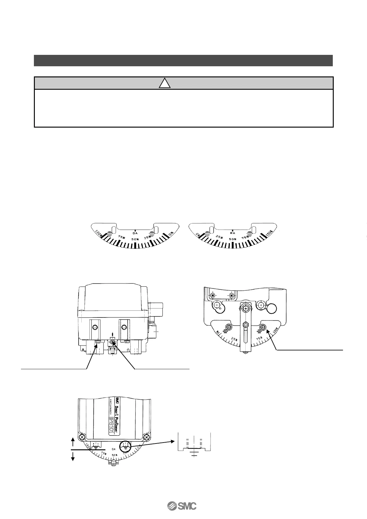
(1) After adjusting the positioner zero/span, mount the scale plate to DA surface (Direct operation)
or RA (Reversed operation) in correct direction (See Fig. 47).
(2) Stop the actuator open degree in the middle (50% of positioner input current), and adjust the
indicator position so that the indicator position match with gauge at 50% (See Fig. 48). If
indicator position does not match with 50% of the gauge even if adjusted, adjust the fork lever
unit angle correctly referring “■Initial Adjustment”
*
1
.
(3) Confirm if the indicator indicate 0% and 100% of the gauge at the start and end of the actuator. If
it does not, loosen the cross recessed socket head screw for mounting to the dial using a
spanner, then slide the scale plate (See Fig. 49, 50).
1: If the fork lever-type fitting angle is
adjusted after calibration, adjust the
span (parameter code: C70).

 Loading...