EasyManuals Logo

SMC Networks IP8101 Series User Manual

SMC Networks IP8101 Series
85 pages
To Next Page IconTo Next Page
To Previous Page IconTo Previous Page
Page #28 background imageLoading...
Page #28 background image
No.DIG-31900-OM002
27
Mode Change on LCD
Mode Change
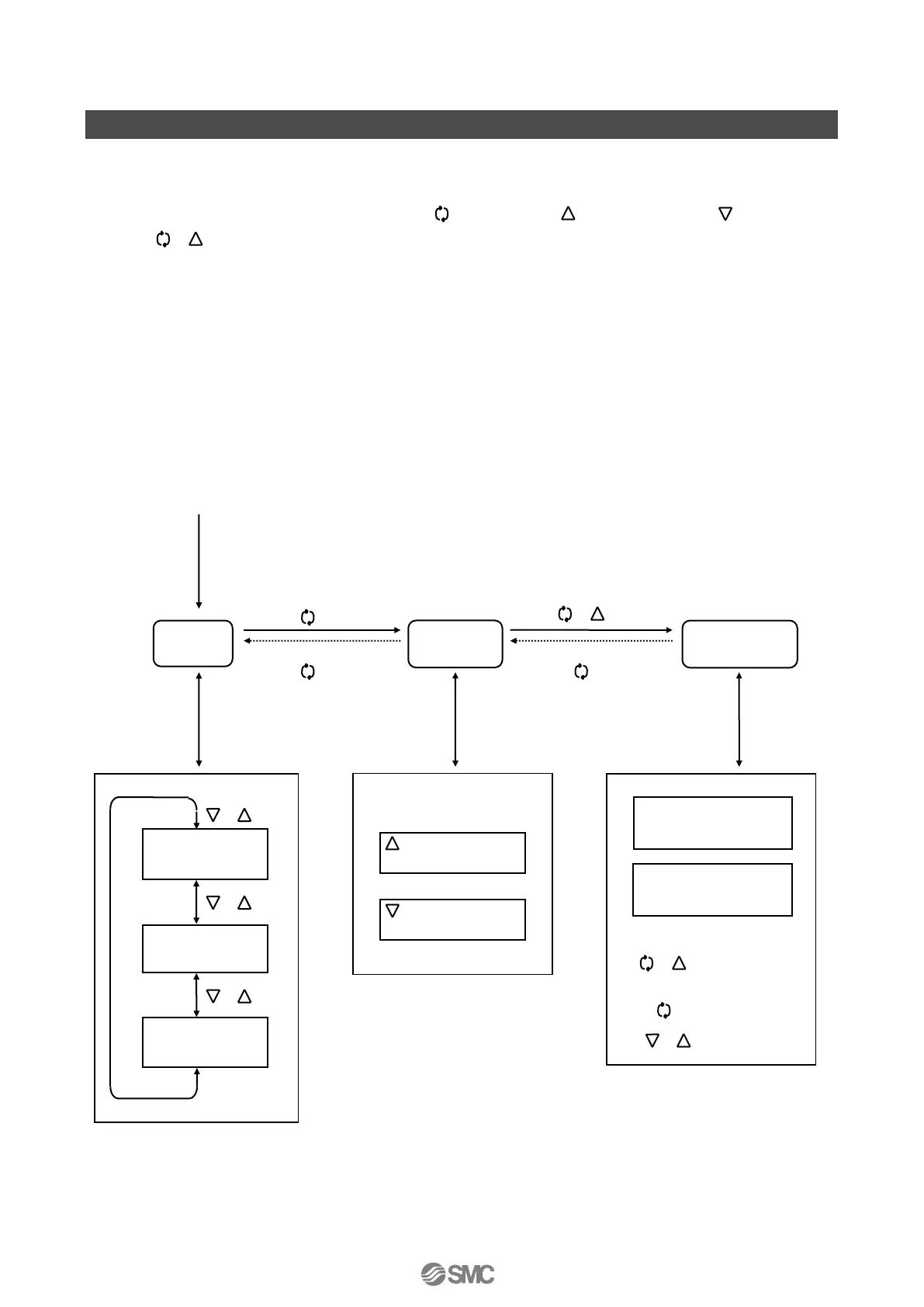
According to Fig. 20, press the mode button ( ), UP button ( ), DOWN button ( ) and set
button to change operation mode.
Parameter Functioning in Manual Mode
For the position indication (P value), zero / span setting (parameter code: 400) functions as it is.
Reflection of Changed Content in Parameter mode
The changed content is reflected at the time when the mode moves from parameter to manual, and
then moves to auto mode
1
.
1: If the input current is cut off during the parameter change, the setting value during the change will be
deleted. In that case, be sure to return to the parameter mode after restarting the potisioner, and check if
the set value is changed. If not, set the value again.
Fig. 20
(Indication level 2)
: Increases input
current
: Decreases input
current
Manual operation
(Indication level 3)
Apply input current
Manual
mode
Auto
mode
(Indication level 1)
Position
P value
Input
S value
Deviation
E value
Parameter
mode
or
or
or
Mode button
3s
Set button
1s
Mode button
1s
Mode button
1s
Mode button
1s
or
Set button
1s
Change
Decide
Select
Various parameter
setting
Calibration
B

Table of Contents

Questions and Answers:

Question and Answer IconNeed help?

Do you have a question about the SMC Networks IP8101 Series and is the answer not in the manual?

SMC Networks IP8101 Series Specifications

General IconGeneral
BrandSMC Networks
ModelIP8101 Series
CategoryValve Positioners
LanguageEnglish

Related product manuals