Mounting
1. Confirm the positioner is securely and firmly mounted onto the actuator.
2. Be careful not to get a finger caught when matching mounting positions.
1. Be sure to keep the necessary space available for maintenance work (piping, wiring,
adjustment, etc.) in your setup location.
2. Cut off the pressure supply to ensure compressed air is discharged from the positioner
and actuator completely before starting mounting.
3. When removing the positioner from the actuator and mounting it onto another actuator,
malfunctions may occur due to its remained initial constant. Therefore, when it is mounted
onto other actuators, transmit the input signal while cutting the air supply, and be sure to
perform Simple balance current adjustment through the calibration mode (parameter
code: C20). Then apply the air while biAS is indicated on the LCD and perform the Simple
balance adjustment (parameter code: C20) and calibration (parameter code: C30).
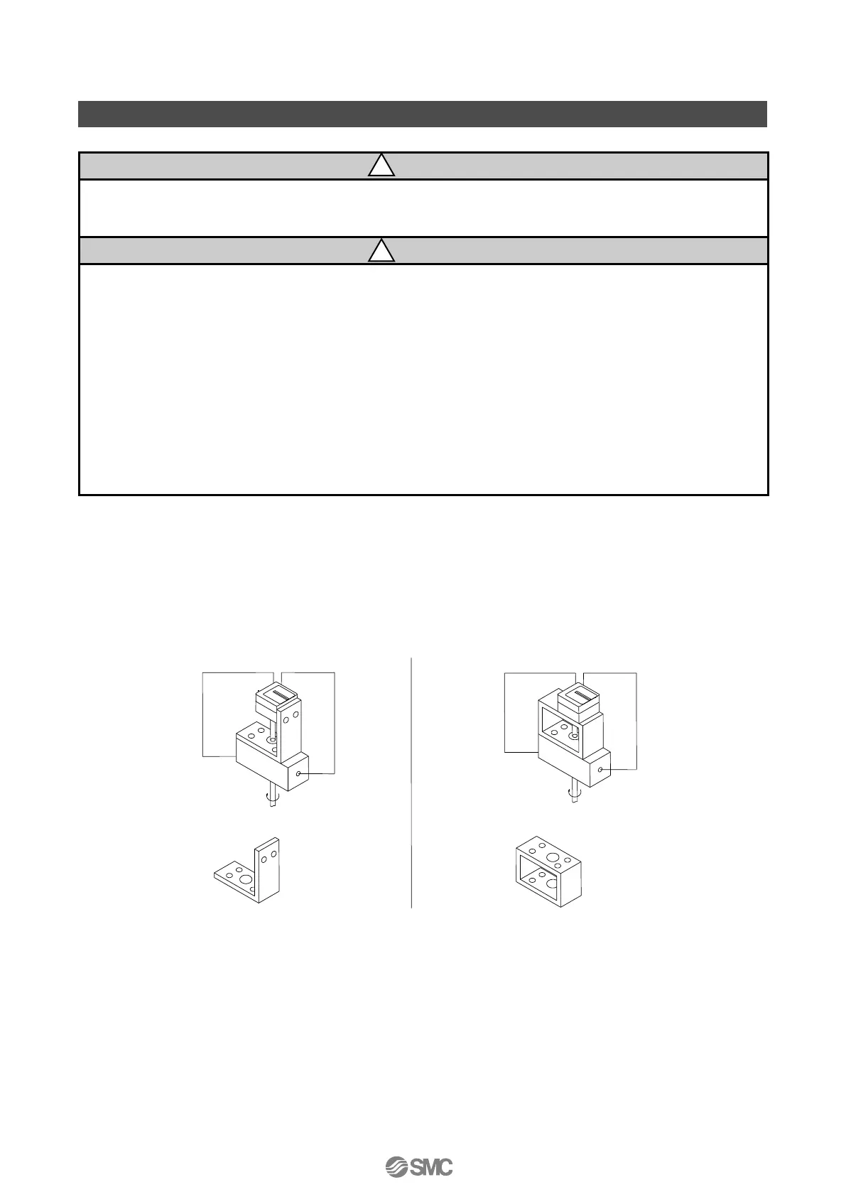
■Example of Mounting on Actuator
IP610, IP6100 and IP8100 offer interchangeability in mounting pitch with IP8101 smart positioner.
Therefore, it is possible to apply a bracket for IP610, IP6100 and IP8100 for mounting
*
1
. However, if
IP6100 is replaced with this positioner and accessory H (with an external scale plate) is selected, it
is necessary to lower the position of the fork lever-type fitting.
1: IP610 and IP6100 have the same mounting pitch as IP8101, but a different mounting height. Watch for
interference between the bracket mounting screw and bottom face of the positioner body.

 Loading...