8
EEWB334A
4-1
4-2
3
1
2
4
5
3a
6
8
2
1
9
7
3b
10
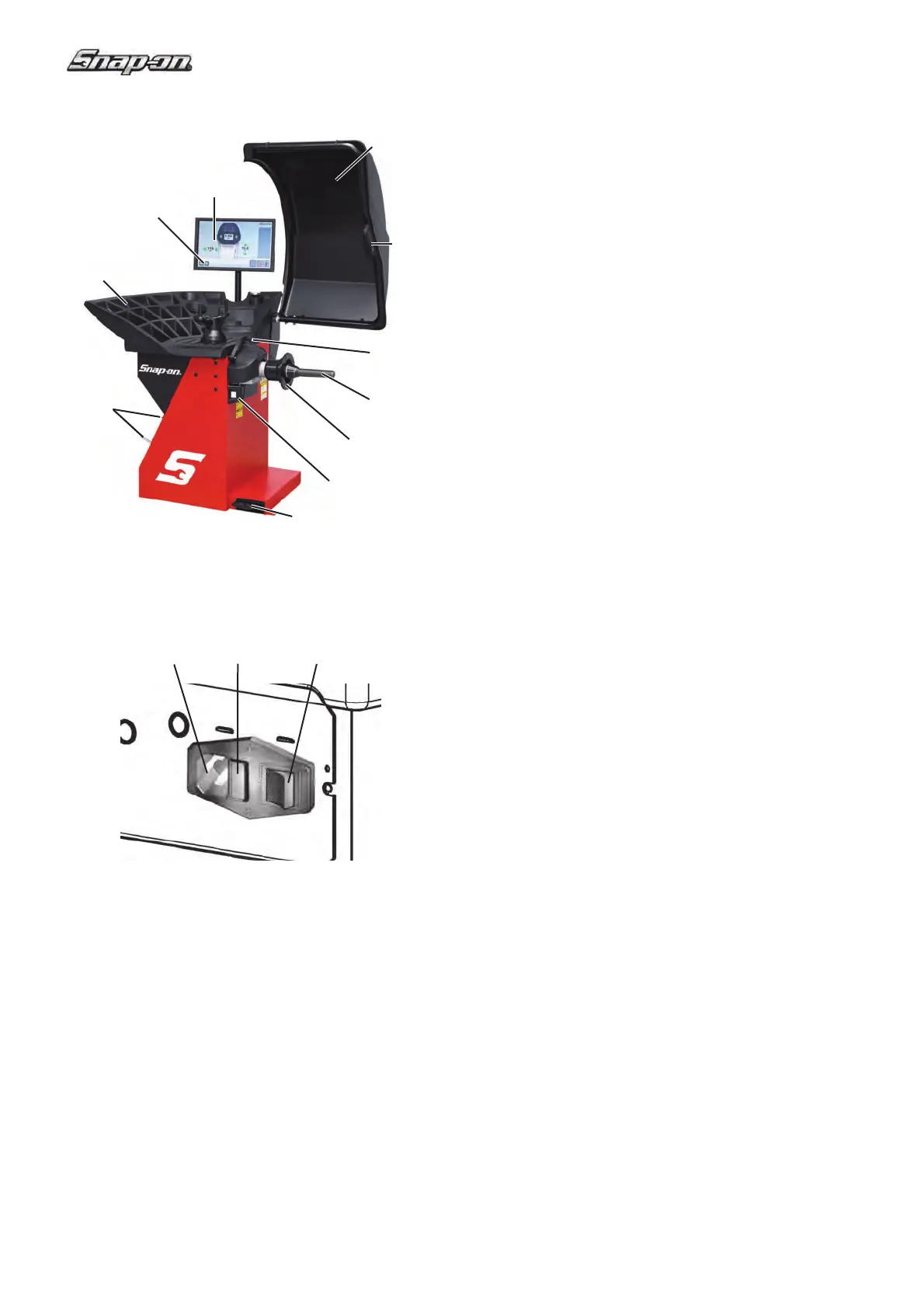
4.0 Layout
Refer to Figure 4-1
Functional description of the unit:
1. Display
Refer to Chapter “The Screen”.
2. Input panel
Refer to Chapter “Basic Commands”
3a.
Internal SAPE arm
3b.
External Detector - Sonar
4. Flange
5. Stub shaft
6. Weights compartments
7. Storage areas for cones and wheel weights
8. Wheel guard
9. Control pedal (Brake)
10. Laser weight placement indicator
Refer to Figure 4-2
1. Main switch (ON/OFF)
2. Fuse holder
3. Power inlet