Scanner Viewing and Saving Data
20
4.5 Viewing and Saving Data
Selecting Data or other similar data menu option (depending on the vehicle
manufacturer) displays PID data for the selected system (Figure 4-12).
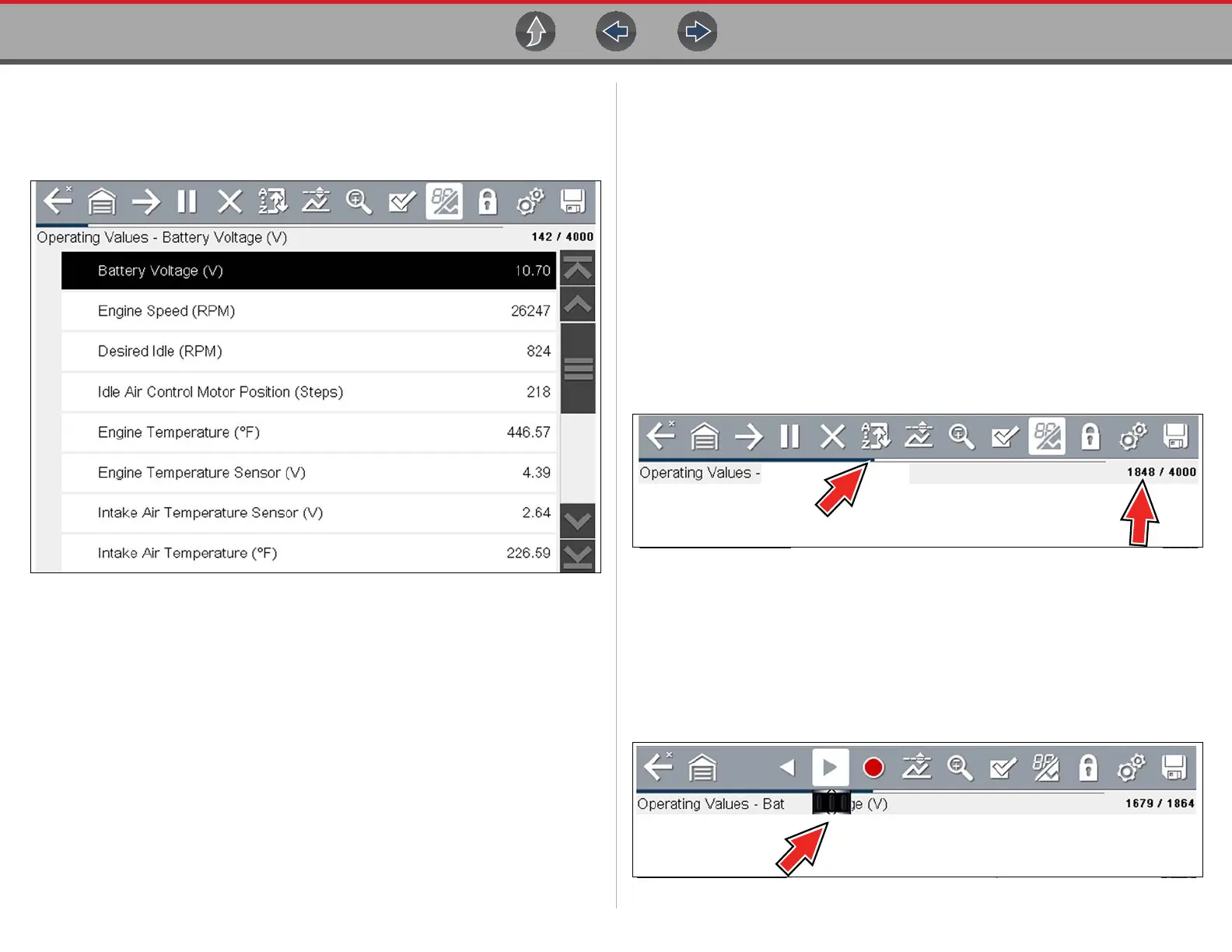
Figure 4-12 Data display (PID List view)
During data display the main body of the screen is divided into two columns; the left-
hand column has a description of the parameter and the right-hand column shows
the current parameter value or state. PIDs are listed in the order in which they are
transmitted by the ECM, so variations between years, makes, and models will occur.
The toolbar control icons are described in Scanner Control Icons on page 12 and
Common Toolbar Control Icons on page 8.
4.5.1 About the Data Buffer
The diagnostic tool has the capability to collect, store and save PID data utilizing
internal storage memory and buffer memory.
When Data is displayed onscreen, a data buffer automatically starts to store it in
buffer memory. The data buffer runs continuously (storing data) until the Pause,
Clear, or Save icon is selected.
Buffer memory is limited to a predetermined “total” size. When buffer memory
reaches it’s full capacity, the data buffer will continue to store new data, however
earlier stored data will be removed to allow room for the new data being stored.
The most recent data is always available for review when Pause is pressed, and can
be reviewed using the toolbar controls.
The Data Buffer Indicator (Figure 4-13 left arrow) can be used to visually see the
amount of stored buffer data. This graphical indicator uses a bar graph to show how
much stored data is in the memory buffer.
Figure 4-13
The Data Buffer Position Counter (Figure 4-13 right arrow) indicates:
– first value = the numerical position of the current frame of data (displayed)
within buffer memory
– second value = indicates the maximum data buffer size value (e.g. 4000)
During data review (Figure 4-14), a slider on the bar graph indicates the position of
the current frame of data (displayed) in relation to the entire memory buffer contents.
Figure 4-14