Scanner Viewing and Saving Data
29
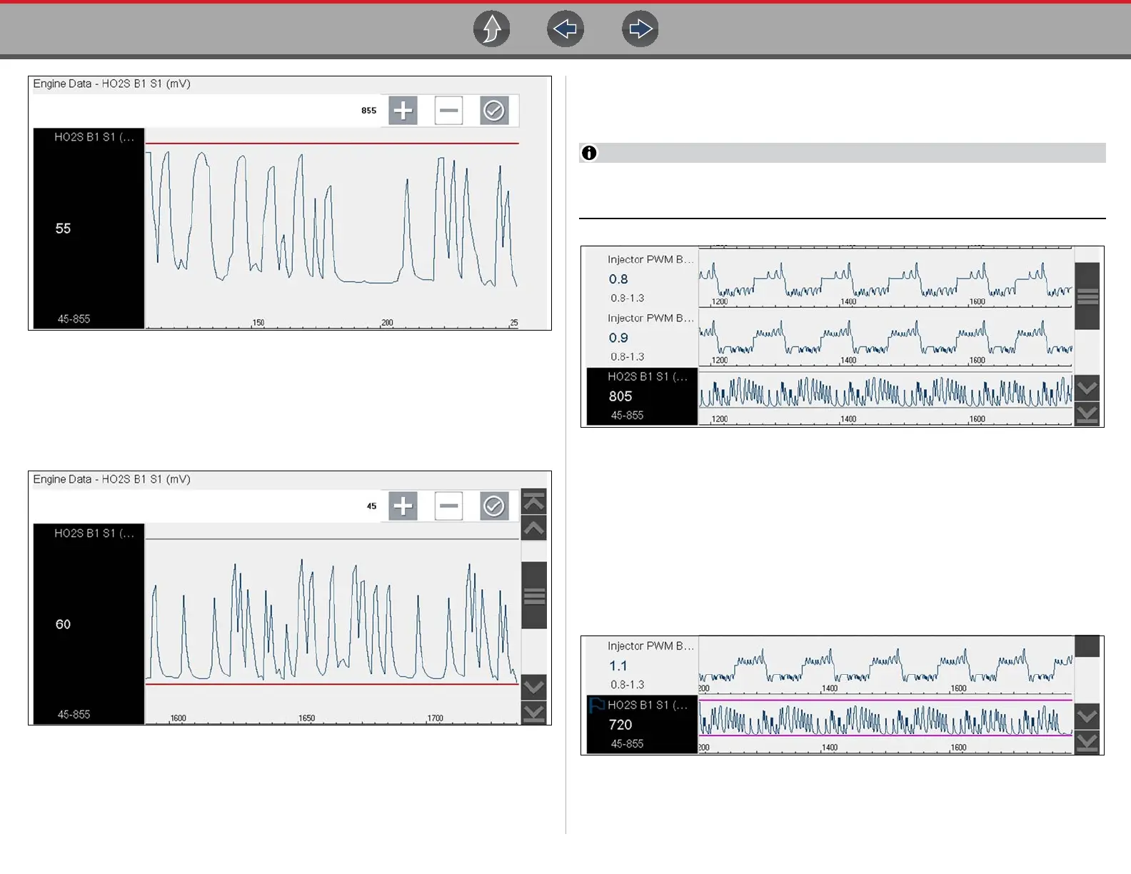
Figure 4-29 Trigger setup - upper limit
The upper trigger line changes color to gray and the lower trigger line displays
in red (Figure 4-30).
6. Change the position of the lower trigger line in the same manner as the upper.
7. When finished, select a, or press the Y/a button, to set the lower trigger level.
Figure 4-30 Trigger setup - lower limit
The display returns to the PID data view and the trigger points appear as horizontal
lines across the designated graph (Figure 4-31). Repeat this procedure to establish
trigger points for other parameters (up to three) if desired.
Only three parameters can have trigger levels set at one time, but only one of
the conditions needs to be satisfied for triggering to occur.
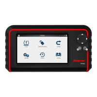
Figure 4-31 Trigger set (not armed)
z Arming triggers:
1. Select the Trigger icon.
2. Select Arm Triggers.
The trigger point lines change color to indicate an armed condition
(Figure 4-32).
All set PID triggers are armed simultaneously (if more that one is set). Once armed it
remains armed until you clear it or the trigger is activated.
Figure 4-32 Trigger armed