Scanner Viewing and Saving Data
28
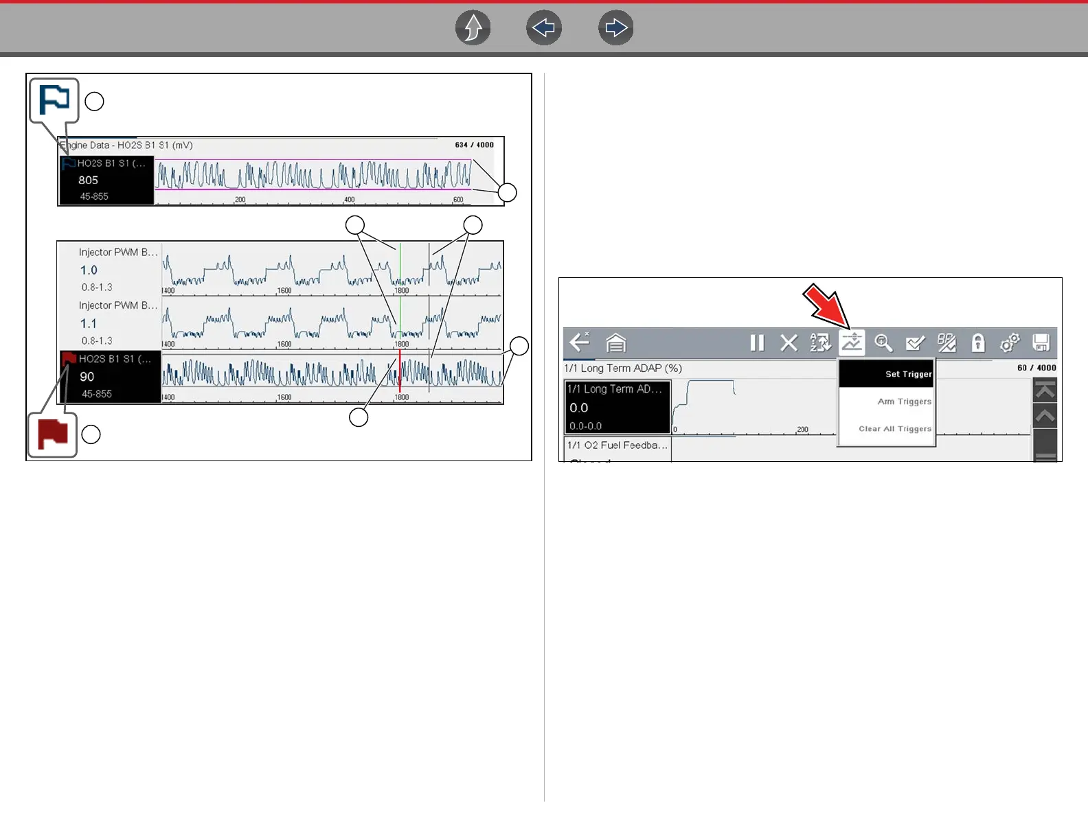
Figure 4-27
1— Armed PID Trigger Indicator - A blue outlined flag indicates the PID trigger
is armed.
2— Upper and Lower Limit Lines (Armed) - Colored limit lines indicate the
trigger is armed but not activated.
3— Trigger Activation Point Reference Cursor - Green cursors lines are
displayed on all the other PID graphs to indicate their relationship to where
the trigger occurred.
4— Pause Cursor - A vertical gray cursor line is displayed (all PIDs) as a marker
in the where the data was paused and the file was saved.
5— Activated PID Trigger Indicator - A red flag indicates the PID trigger has
activated.
6— Trigger Activation Point Cursor - A red cursor line is displayed in the PID
data where the trigger was activated.
7— Upper and Lower Limit Lines (Not Armed and Activated) - Gray limit lines
are displayed when the trigger is armed but not activated and after the trigger
has been activated.
z Setting triggers:
To use triggers, they must be turned on (set/configured), and then armed. Use the
following procedures to setup PID triggers.
1. Highlight the PID to setup with a trigger.
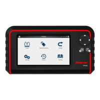
2. Select the Trigger icon.
Selecting the Trigger icon (Figure 4-28) displays trigger menu options:
- Set Trigger—opens setup screen for upper/lower limits (trigger points)
- Arm Trigger—arms the trigger to capture data
- Clear All Triggers—deletes all previously set triggers
Figure 4-28 Trigger menu
If triggers are already set, the menu options are:
- Clear Trigger—deletes the highlighted trigger
- Disarm Trigger—disarms the highlighted trigger
- Clear All Triggers—deletes all set triggers
3. Select Set Trigger.
A graph of the highlighted PID and setup icons display (Figure 4-29).
The upper trigger point must be set first. A red horizontal line is displayed
across the data graph (Figure 4-29) representing the upper trigger point.
4. Use the plus (+) and minus (–) icons (Figure 4-29), or the up b and down d
arrow buttons to change the position of the upper trigger point.
5. Select a, or press the Y/a button, to set the upper trigger point.