V3400 Service
68
ESTABLISHING COMMUNICATIONS WITH THE CAMERAS
When the camera towers are rst powered up you will note one green LED that indicates DC power supplied
to the pods. Once the pods boot up you will note a slow “rotating strobe”. The “rotating strobe” are the LEDs
in each camera board that ash in a circle indicting the level of connection. When the camera makes commu-
nication contact with the PC radio, the rotating strobe go to a fast mode. The fast mode will be maintained on
home screen only until the cameras are required to “see” a target and relay information to the PC. At this time
the lights that are relevant to the target condition are shown steadily. When the pods are receiving a rmware
update the “rotating strobe” are in the superfast mode.
When all three cameras make communication contact with the PC, both pods go to the bottom most position
or home where they establish a reference point for left camera pod to right camera pod position. As soon as
the software invokes a command that requires the cameras to see a target the pods go to the search mode.
This search mode is much faster and smoother than past models and will not stop and go as much.
As in all other Pro42 variants, the operation of the software is pretty much the same and little has changed.
However with the new cameras and targets we must properly set the system up for the hardware.
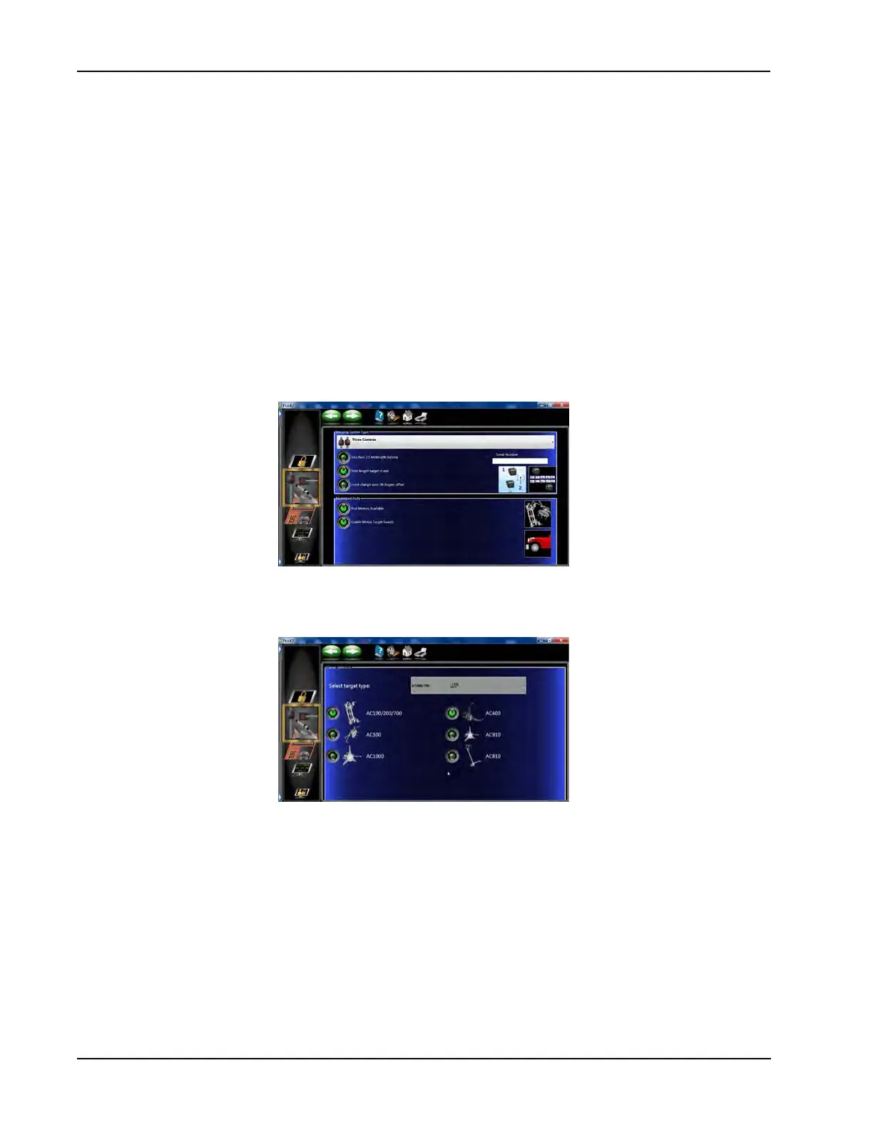
Select the camera system
From the “Preferences” screen select “System Conguration”. Select “Three Cameras”.
Note: Ride Height targets are shipped standard with the V3400 Aligner Systems.
Activate all clamp types to be used in the system. If only one clamp type is selected you will not be asked
which clamp is being used before performing compensation. If more than one clamp is selected you will
choose which clamp will be used for the procedures.
The V3400 can utilize either the AT600 targets or standard AT700 targets. Only one target type can be se-
lected for each system. Multiple clamp types can be selected. The system will have a separate TID called for
each clamp-target assembly.