16
Theory of Operation
TARGETS 3D
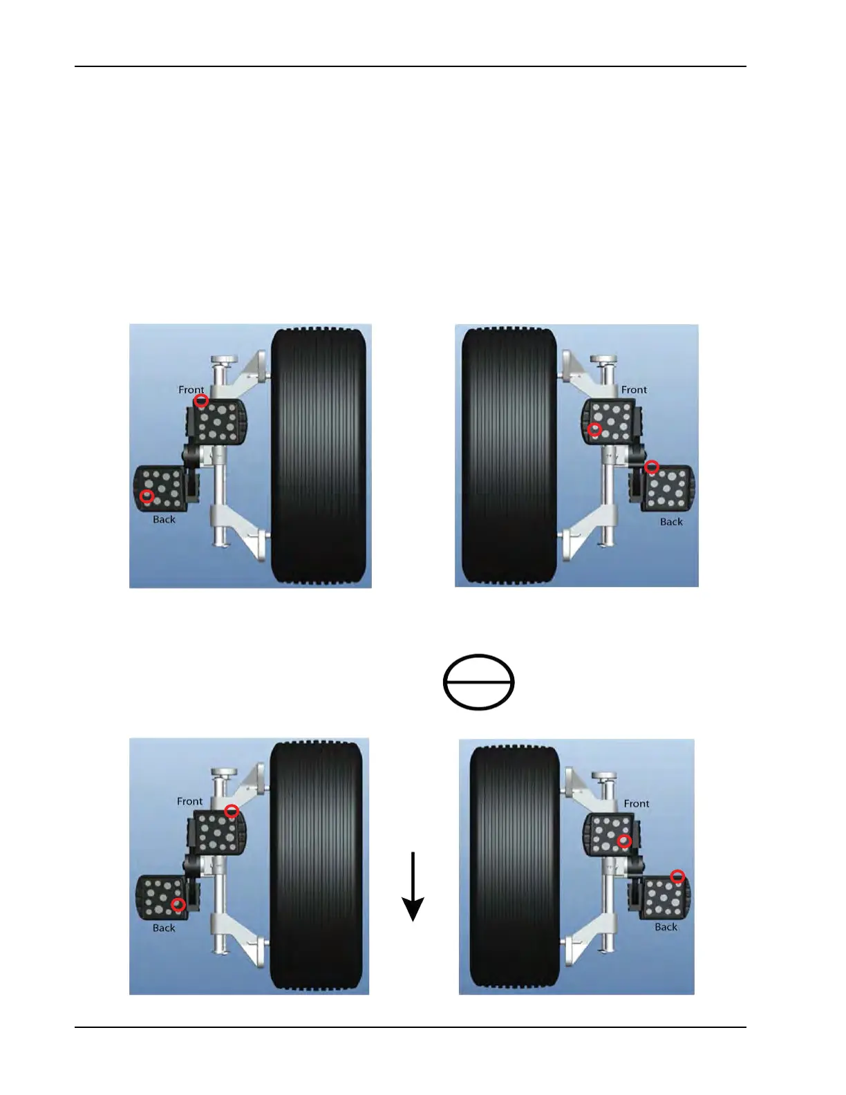
The new 3D targets are unique for each wheel. The rotation of the sub targets denes the wheel position. A
quick glance at the targets the operator may think that both left targets are identical and both right targets are
identical. However the illustration below displays the difference of each set of targets to each wheel. Looking
at the identication dot on each target you will notice that on each wheel it is in a different location as it is also
in a different location one each set of targets. This location tells the camera which of the targets from the set
is a back and which is a front target. From the target assembly the back target on each wheel is the Master
target. Locate the dot on each master target and you will notice that the dot on the front target is turned either
90º CW or 90º CCW from the Master target. Each target contains a total of 13 ds (5 large and 8 small) this
brings the target set to a total of 26 ds. No more that 3 small ds can be blocked on any target before it is
lost in the cameras eld of view and none of the large ds can be blocked before it is lost in the cameras eld
of view. Relative Target Position (RTP) is stored on the camera so each target is married to the camera that
sees it. The RTP is restored from backup information if used.
Conguration using conventional wheel clamp