23
Theory of Operation
POSITIONING SEQUENCE
The 3D Aligner knows where the targets are, but it does not yet know where the vehicle is. Of course, the
targets are attached to the vehicle’s wheels, and this provides the link to the vehicle’s alignment angles. The
term “wheel alignment” is a bit misleading. We don’t adjust the wheels, we adjust the suspension and steer-
ing components, resulting in changes at the wheel. It is the vehicle “spindle” that receives the alignment, and
the wheels are just along for the ride. All wheel alignment equipment uses the spindle as a starting point,
usually by either placing the measuring device directly opposite the spindle or by performing a runout com-
pensation referencing gravity or the rack. The 3D Aligner nds the spindles in a unique way that improves
accuracy and speed.
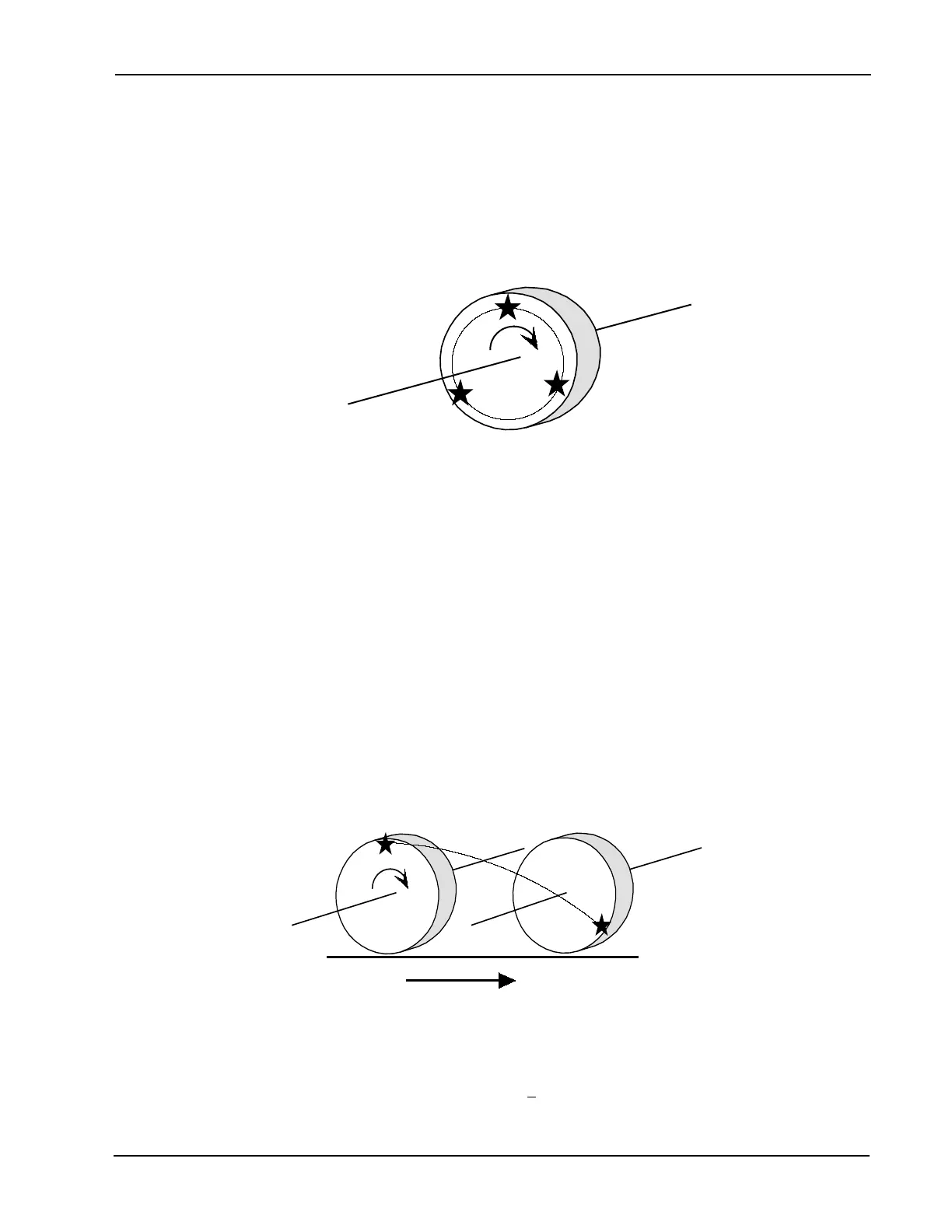
Movement of a Point During Positioning
A single point on the wheel/tire is represented by the star. If we rotate the wheel/tire and track the position of
the star at various points we would nd the star movement forms a circle. If we determine the center of the
circle we have dened the axis of rotation of the wheel/tire. In automotive terms, the axis of rotation of the
wheel is called the spindle.
The 3D Aligner locates the vehicle spindles directly using a procedure called positioning. In positioning, we
rotate the wheel/tire/target by rolling the vehicle. As the vehicle moves, the cameras track the location and
orientation of the target dots. If the wheel went through a complete 360-degree rotation each dot would scribe
a circle as illustrated in the picture below. If we took our scribed circle and determined where the center of
that circle was located, we would nd the spindle. The dot moves back as well as rotating about the axis, this
allows the software to locate the spindle position in 3 dimensions with respect to the camera.
Of course there is more than one point on our targets that the cameras can track, there are 33 reective dots.
As we move the car, each dot is tracked for distance and orientation, with the software using this data to cre-
ate 33 circles of different sizes. Each circle is then analyzed for the center point, with the results averaged
to determine the vehicle’s spindle. Since there is a target on each wheel the software nds each of the 4
spindles simultaneously.
In the last paragraphs the positioning sequence described the targets dots scribing a circle through a 360-de-
gree rotation of the wheel. In reality, this is not practical a full wheel rotation would require a roll back of 5 to
7 feet, depending on the circumference of the tire. Most alignment racks cannot handle this. The engineers
were able to shorten the wheel rotation angle to 35-degrees + 5. This works out to 6 to 10 inches of vehicle
roll, which is easy to accomplish with most vehicles.