V3400 Service
70
If replacing a target, or clamp, TID or single bar calibration will be required. It is recommended that single bar
be performed, however if a customer is doing the work TID will sufce.
NOTE: NEVER PERFORM TID AFTER DOING A SINGLE BAR CALIBRATION. DOING SO WILL DELETE
THE OFFSETS FOR TOTAL TOE AND CAMBER.
Motor calibration is not used with the V3400, the upper and lower limit switches have been removed. The
end of travel is sensed by current change detection. Also when the pods are not engaged, there is an elec-
tric brake that prevents the pods from moving freely. However if you need to move a pod for some reason,
press downward rmly for a few seconds and the software determines that the user wants to move them and
releases the brake. Motors will not move for 30 seconds after manual movement. The brake will re-engage
after 30 seconds. Pod lever calibration has also been removed.
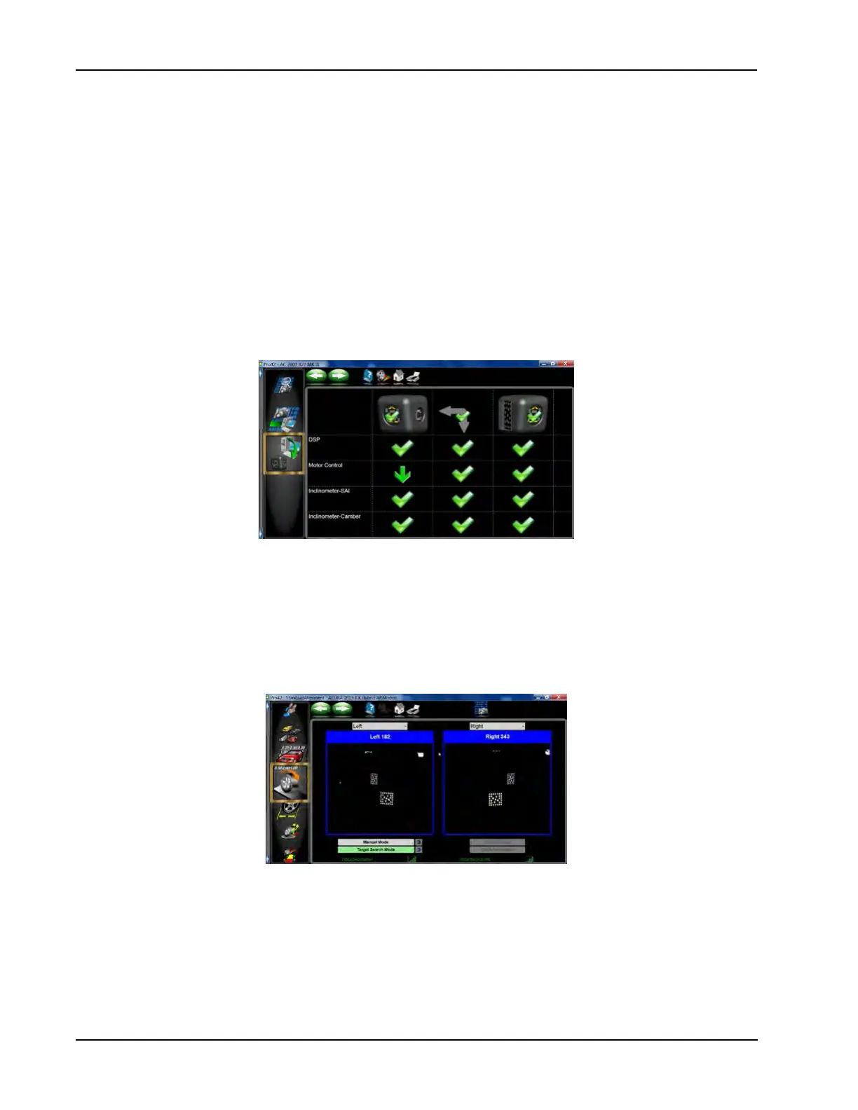
CHECKING THE FIRMWARE
From the home screen select “Diagnostics” from the left carrousel bar. Then select “Check Firmware” located
at the bottom of the carrousel.
When invoked the system checks the revision level of the cameras and controller rmware and compares to
the currently loaded Pro42 version. If there are updates available it will be indicated by a green arrow. The
green check mark indicates version is good. A red X indicated a loss of communications.
Note: Multiple updates can be performed simultaneously. The load process takes about 8 minutes.
CAMERA DIAGNOSTICS
The various Camera Diagnostics screens have not changed much from previous versions of Pro42. A few
added features assist the technician with diagnosing problem areas.
Camera View - The camera view may be noticeably grainier than previous versions of Pro42. This is normal
and not a result of the camera resolution. We are only displaying what is necessary to verify target position
and ensure targets are in the optimal position.
Notice the radio signal strength indicator bars at the bottom of each camera view. Also displayed is the cam-
era ID number.
NOTE: WITH THIS CAMERA VIEW, THE DRIVE-ON ASSIST CANNOT BE USED UNLESS AN AFTER-
MARKET WEB-CAM IS ADDED TO THE SYSTEM.