V3400 Service
72
SERVICING POD COMPONENTS
Pod covers are constructed in three pieces allowing the technician to only remove the section covering the
component to be serviced. Each pod cover section is secured with two phillips screws on the top and two on
the bottom.
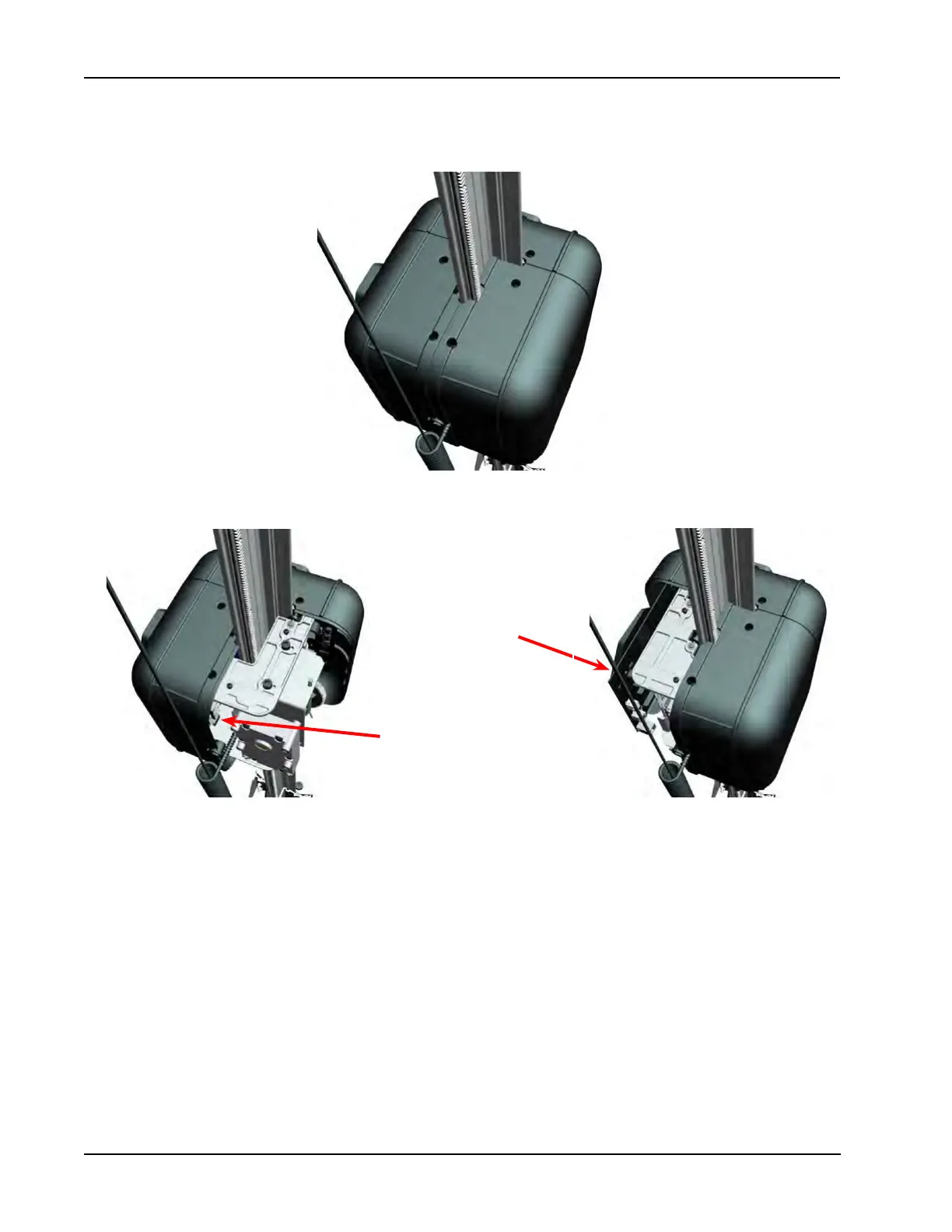
This illustration shows the cam-cam pod with two covers removed. The outside pod cover is removed to allow
access to the motor controller board.
The cover to the inside or facing the cam-targ pod is removed to allow access to the calibration camera.
The front cover is removed for serving the measurement camera. Removal of the front camera cover is eased
a small amount if one of the side covers is removed rst.
If pod covers are removed, make sure the coiled cable strain relief is properly placed between the pod covers.
Calibration Camera
to be serviced
Motor Controller to be
serviced