Normal View of Circle - Moving Away
Y
X
21
Theory of Operation
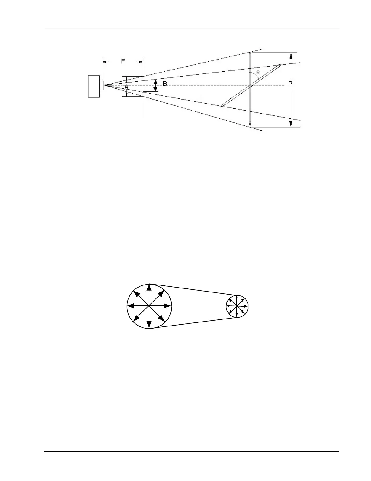
In this example, the camera is at a xed point in space. All xed camera lenses have a xed focal
point. The distance from the camera to the focal point is a known value F, created by the designers of the
lens. The size of the pen is a known value P, created by the designers of the pen. The observed size of the
pen is measured by our “software” at the focal point and becomes a known value B. The goal of this exercise
is to determine the angle of orientation R away from the normal position.
THE CIRCLE
Hopefully by now we have some understanding of how the 3D Aligner can determine how far away the targets
are and their angle of orientation. Of course, when placed on a vehicle the dots are likely to be at varying dis-
tances from the cameras and at varying angles or orientation at any given moment. An observer to the above
may ask, “how can the aligner tell the difference between the effects of perspective and foreshortening? All
it knows is the targets images are smaller than their actual size. What about orientation changes in 3 dimen-
sions?”. The answer is a powerful geometric shape, the circle. As you will nd out, the circle was chosen as
the geometric shape for the targets because of its mathematical relationships. For this discussion, assume
the aligner targets consist of a single large dot.
Focal Length (xed by lens) Pen (known length xed)
Normal View of Circle - Moving Away
The circle has some unique characteristics that make it useful for the 3D Aligner. When you look at a circle
from the normal position (straight on, or a 90-degree angle), the diameter across is equal no matter where it
is measured. As the circle moves away from you, the diameters appear to get smaller due to the effects of
perspective as discussed earlier.