V3400 Service
73
REPLACEMENT OF POD COMPONENTS
CAMERA REPLACEMENT
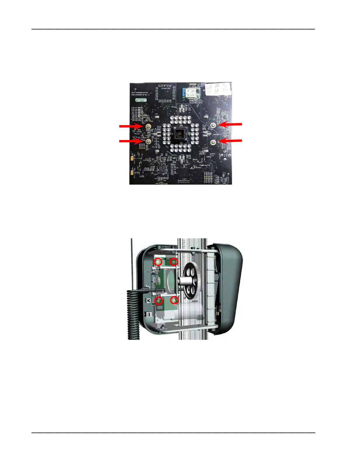
To remove pod components, rst identify the part in question and remove that section of pod cover. To
remove a camera board, rst disconnect the power and control cables. Only the measurement cameras will
have motor control cables, the calibration camera has only a power cable connected. Next remove the four
phillips screws near the center of the board. Replace with service board in the reverse order followed by per-
forming RCP.
REPLACING THE MOTOR CONTROLLER
Remove the outside pod cover. Disconnect control and power cables from the board. To remove the Motor
Controller Board, use a long shank phillips screwdriver to access the four screws securing the board to the
pod chassis. Re-install service board in the reverse order.
NOTE: If the left side camera
is replaced the security key
will be required to be used to
activate the camera and load
security to the camera before
use. Reference instructions
TEAK0277J97C.