V3400 Service
71
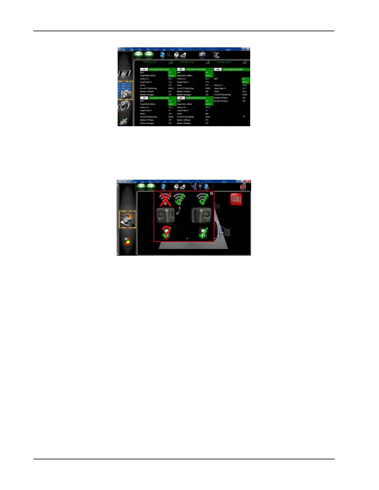
Also the measurement data screen indicates the relative signal strength and ID of the cameras as well.
DISCONNECTED CAMERA
In the event a camera loses communication with the PC during a live screen such as rollback, readings or
adjust. A new pop-up screen appears that indicates which camera has been dropped.
The screen alerts the operator to check the power and see if the LEDs are working on the camera(s) dis-
played.
If both cameras on the left side disconnected, the power would be suspect, however if only one camera is
shown to be disconnected then look for an obstruction or other issues. The power source indicator will be
displayed with a green check if any one of the two are connected.
If the pods are not level it is possible to force a calibration of pod level by going into “Camera View” and send-
ing the pods to the bottom manually for 10 seconds. This should happen during normal operation. Make sure
the Cal Target is visible when the pods are at the bottom of the supports.