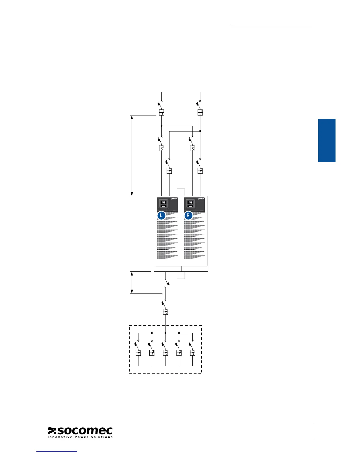
➐
L R
MAINS AUXILIARY MAINS
RECOMMENDED PARALLEL 1+1 REDUNDANT CONFIGURATION
For the electrical connections refer to page 60.
Legend.
1 Main di erentialmagneto-thermal
switch.
2 Magneto-thermal switch.
3 “Parallel bus” cable.
4 Output switch.
5 System shutdown switch.
6 Distribution.
7 Power connections (refer to page 60)
L Left UPS
R Right UPS