56
Wiring
Inverter
Right electrical
connection area
Two adjacent
battery modules
Left electrical
connection area
2
1
3
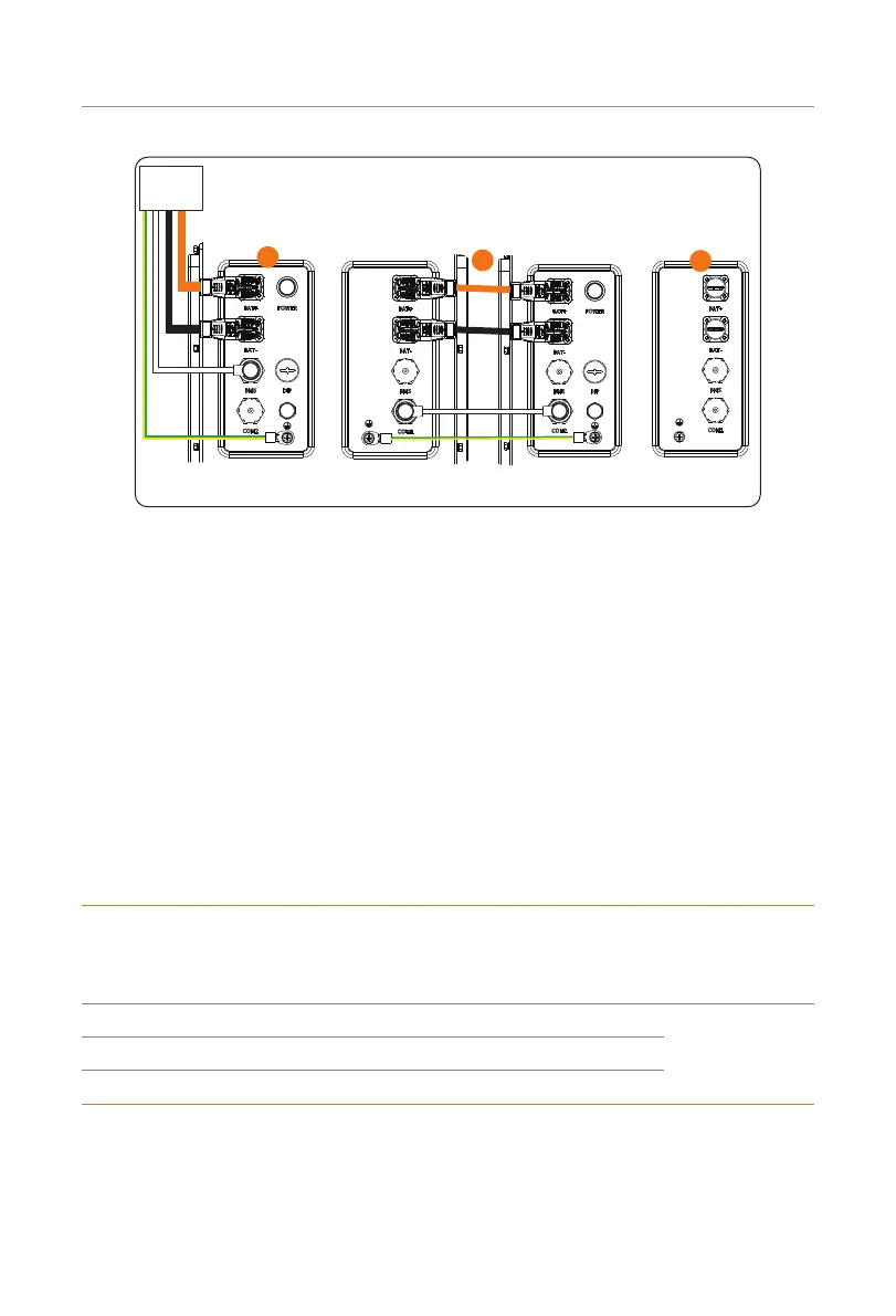
Figure 7-19 Wiring diagram of two battery modules
The detailed connection procedure is shown as follows:
Step 1: Connect the negative power cable to the "BAT-" ports of the battery module and
inverter.
Connect the positive power cable to the "BAT+" port of the battery module and
inverter.
Connect the communication cable to the "BMS" port of the battery module and
inverter.
Cover the "COM2" port with a waterproof cap, and tighten it clockwise.
Make sure that power cables and communication cable are wired correctly, as
shown in Figure 7-20. Failing to do so may cause severe damage to your battery
module.
Table 7-3 Cable information
Cable Length
Purpose
(incl
.
from battery module to
inverter, battery module to
battery module)
Qty
Communication cable 2000 mm "BMS" port to "BMS" port
According
to the actual
number of the
battery modules
Power cable (black) 2000 mm "BAT-" port to "BAT-" port
Power cable (orange) 2000 mm "BAT+" port to "BAT+" port
 Loading...


