49
Wiring
NOTICE!
• Properly place the ring terminal into the MC4 crimping tool.
Step 3: Make the positive power cable according to the above two steps.
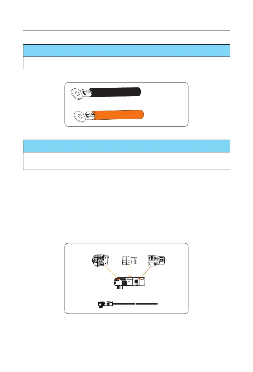
Negative power cable
Positive power cable
Figure 7-9 Making power cables
NOTICE!
• The ring terminals are delivered with the inverter's accessories kit.
• Please refer to the inverter's User Manual for futher installation steps.
7.5 Female Connector Installation
A power cable consists of a flexible cord with connectors, male and female. Since the
power cables provided are only attached to the male connector, the female connector
must be installed onto the power cable by the user himself/herself before conducting
wiring between battery modules. The installation procedure of female connector onto the
power cable is shown as follows:
Step 1: Take out the power cables (Parts A and B), and connectors (Part A1) (including
connector body, cable seal ring, and tail cover).
Connector
Connector body
Cable seal
ring Tail cover
Negative power cable
Figure 7-10 Taking out accessories
Step 2: Orderly insert the stripped wire into the tail cover and cable seal ring.

 Loading...


