47
Wiring
7.3 Communication Connection
To ensure normal operation between the battery module and inverter, the communication
cable connecting from the battery module to the inverter is required to connect RJ45
connector.
Make sure that the "BMS" port on the battery module connects to the inverter is Pin to Pin.
The "BMS" port pin assignment is shown as follows:
Table 7-1 “BMS” port pin assignment
PIN 1 2 3 4 5 6 7 8
BMS RS485B RS485A GND CAN-H CAN-L 12V-OUT MASTER-IN /
The wire sequence of one terminal connecting to the inverter is the same as the wire
sequence of the other terminal, connecting to the battery module.
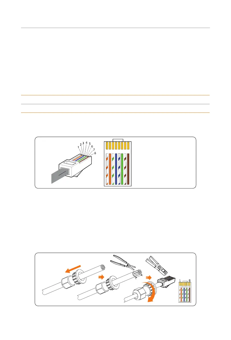
The wire sequence is shown as follows:
1) White with orange stripes
2) Orange
3) White with green stripes
4) Blue
5) White with blue stripes
6) Green
7) White with brown stripes
8) Brown
1 2
3
4
5
6 7 8
Figure 7-5 Wire sequence
The steps for making RJ45 connector to communication cable (Part C) are shown as
follows:
Step 1: Strip the cable jacket about 15 mm down from the end.
Step 2: Carefully insert the wires all the way into the RJ45 connector, making sure that
each wire passes through the appropriate guides inside the connector.
Step 3: Push the RJ45 inside the crimping tool and squeeze the crimper all the way
down.
Rotate clockwise
to loosen
15 mm
Figure 7-6 Making RJ45 connector to communication cable

 Loading...


