52
Wiring
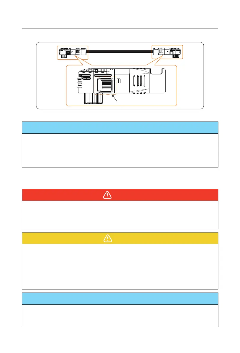
Lock button
Figure 7-16 Lock button
NOTICE!
• The Figure 7-16 is the power cable that finishes the installation of the female
connector.
• Press and hold the "Lock button" while unplugging the power cable. Otherwise, it
cannot be pulled out.
• Don't violently remove the power cables when they are locked.
7.6 Wiring Procedure
WARNING!
• Only the qualified personnel can perform the wiring.
• Follow this manual to wire connection. The device damage caused by incorrect
cabling is not in the scope of warranty.
• Inspect each terminal for visual signs of mechanical defects.
CAUTION!
• Use insulated tools and wear individual protective tools when connecting cables.
• Do not bend the power cable, particularly at the point where the cable joins the
connector, at 90° while conducting wiring.
• When the cable insulation layer is chewed through, this can cause short circuits and
potentially start an electrical fire. Therefore, where there is a risk of pests, rodents, or
termites, protective barriers or additives are suggested to be added to the cables to
prevent damage.
NOTICE!
• The electrical connection areas on both sides of the battery module are allowed to
conduct wiring with the inverter.
• The wiring procedure applies to both floor mounting and wall mounting.

 Loading...


