63
Wiring
Cable connection for two or more battery modules
Since the wiring procedure of two battery modules is the same as that of more than two
battery modules, the wiring procedure of two battery modules is taken as an example.
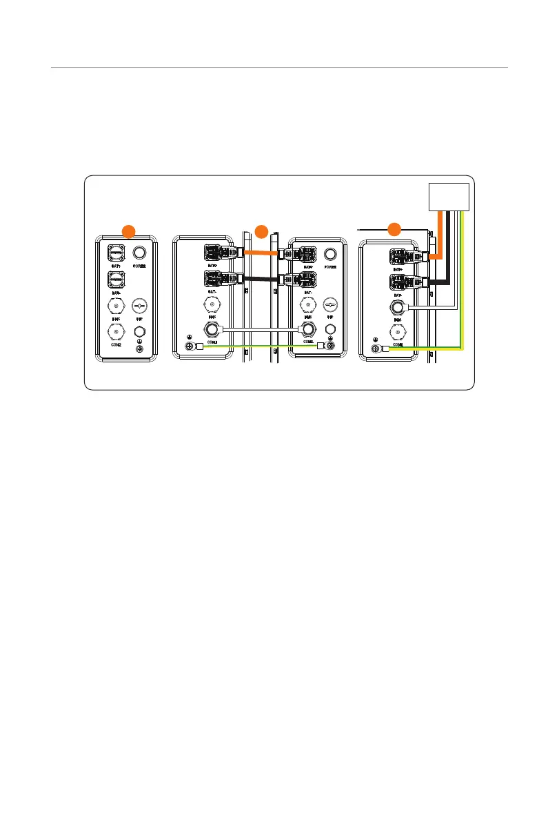
The general wiring diagram of two battery modules is shown below:
Right electrical
connection area
Two adjacent
battery modules
Left electrical
connection area
Inverter
2
1
3
Figure 7-25 Wiring diagram of two battery module
The detailed connection procedure is shown as follows:
Step 1: Connect the negative power cable to the "BAT-" ports of the battery module and
inverter.
Connect the positive power cable to the "BAT+" ports of the battery module and
inverter.
Connect the communication cable to the "BMS" ports of the battery module and
inverter.
Cover the "COM1" port with a waterproof cap (Part E), and tighten it clockwise.
Make sure that power cables and communication cable are wired correctly, as
shown in Figure 7-26. Failing to do so may cause severe damage to your battery
module.

 Loading...


