User Manual
3.4.3.2 Wiring procedure
CAUTION
RISK OF ELECTRIC SHOCK. Prior to starting the wiring procedure, ensure
that the three-pole circuit breaker is switched off and are LOTO.
NOTE
Damage or destruction of the inverter's electronic components due to
moisture and dust intrusion will occur if the enclosure opening is enlarged.
CAUTION
Risk of fire if two conductors are connected to one terminal. If a
connection of two conductors to a terminal is made, a fire can occur.
NEVER CONNECT MORE THAN ONE CONDUCTOR PER TERMINAL.
NOTE
Use M10 crimp terminals to connect to the inverter AC terminals.
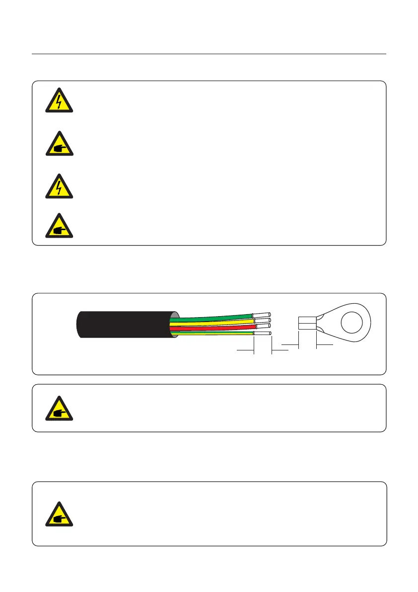
Figure 3.25 Strip AC cable
PE
L
}
S2
S1
NOTE
S2 (insulation stripping length) is 2mm-3mm longer than S1.
(OT cable terminal crimping area)
2. Strip the insulation of the wire past the cable crimping area of the OT terminal, then use a
hydraulic crimp tool to crimp the terminal. The crimped portion of the terminal must be
insulated with heat shrinkable tube or insulating tape.
1. Strip the end of AC cable insulating jacket about 11.8 inch then strip the end of each wire.
(See figure 3.25)
The steps to assemble the AC grid terminals are listed as follows:
NOTE
If choosing aluminum alloy cable, you must use copper-aluminum transfer
terminal or anti-oxdant grease in order to avoid oxidation of the connection
from direct contact between aluminum and copper. (Please select a copper
aluminum transfer terminal based on your cable specification).
3. Installation
27