44
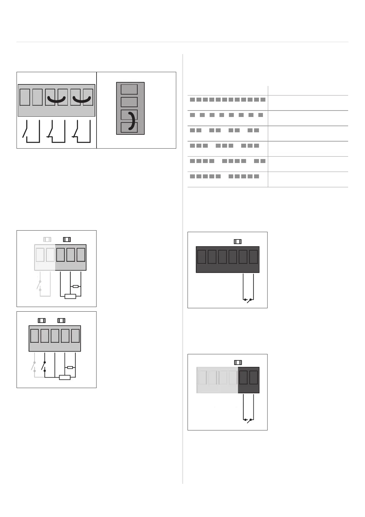
14.3 Checking the wiring of any
unused inputs
IMP
ARS
STOP
CLOSE
OPEN
STOP
COM
The following terminal pairs must be connected to each
other with wire jumpers or normally closed (NC) contacts:
• Locking mechanism
• STOP button
• STOP button of the
external command device
14.4 Connecting a safety contact strip
(8K2 or OSE)
+12 V
VES
8K2
gn
bn
12V
wh
OSE
VE
VES
8K2
gn
bn
12V
wh
OSE
ye
Connection of OSE or 8k2 with pre-end position switch at 4-wire
spiral cable
► No settings need to be made on the control unit. The
control unit tests and recognises which safety contact
strip variant is connected during each self-test (when
the mains voltage is switched on or an end position
has been reached).
14. Brief instructions
► Fortestpurposes,the8.2kΩresistorincludedinthe
scope of delivery can be connected to the terminals
of terminal strip X5. See “8.5 Setting the run time
(run time monitoring)” on page 23 . If the LED on
the safety input still blinks, consult the table below:
Flash sequences Possible cause
• Photocell interrupted/
defective
• Door moves in CLOSE/
OPEN direction
• Safety contact strip
triggered/defective
• Programmed motor run
time exceeded
• Locking mechanism
triggered
• Hardware error on circuit
board
Integrated lighting
14.5 Connection of one-way photocell
with potential-free relay contact
(NC)
24V
GND
24V
GND
SIGNAL
COM
X4
* The control unit provides a total of max. 300 mA / 7 W for all 24 V
consumers
14.6 Connection of 2-wire frame
photocell
24V
GND
24V
GND
SIGNAL
COM
N
N
X4