6 Acquiring Images
90 Basic User Manual
s
cm/s
50
-50
0
5
10
15
X axis: time
Y axis: frequency
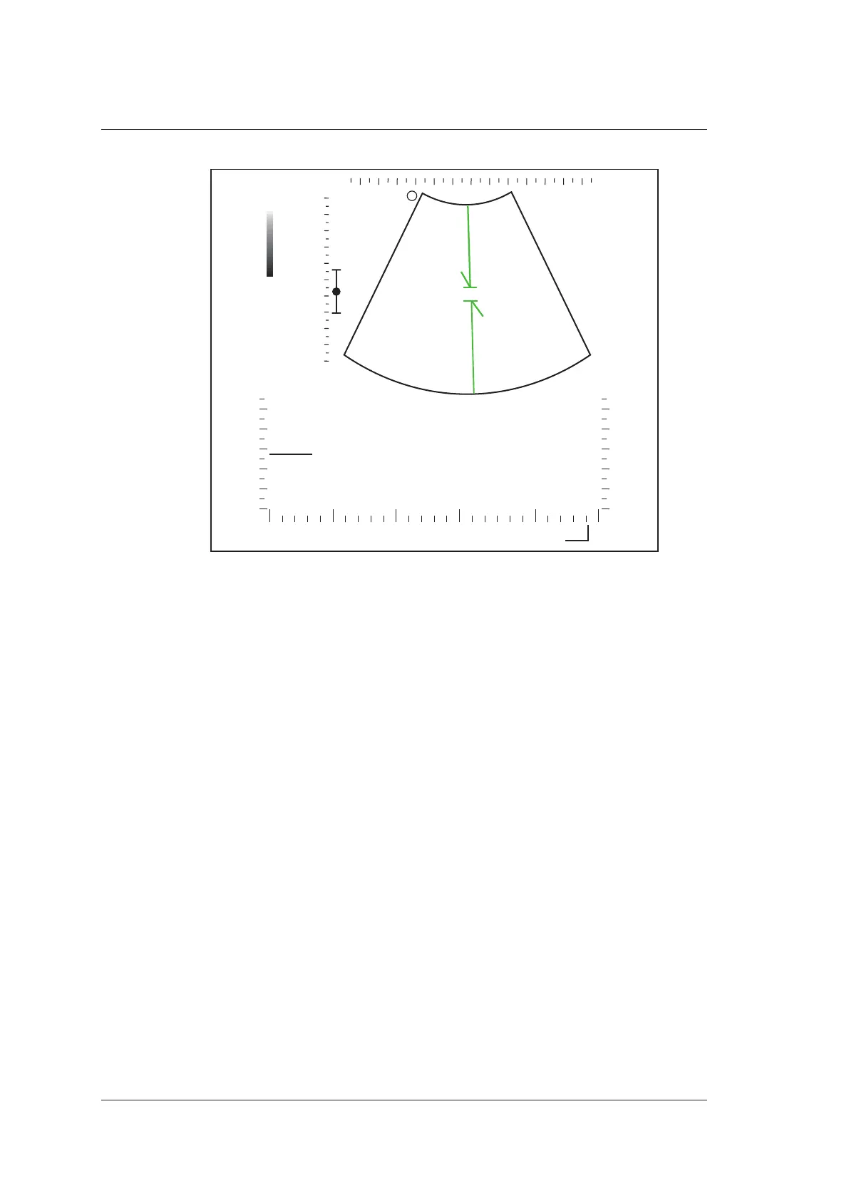
Figure 6-9 Inactivated B+PW Mode 2 Imaging Screen
You can also adjust the position and angle of spectral Doppler line, the size of sample
volume gate, and the direction of the flow cursor.
8. Press the PW key to exit.
6.4.2 Optimizing Spectral Doppler Images
After activating the PW mode, the imaging parameters display at the bottom of the LCD
monitor.
To optimize the image as follows,
●
Press the function key on the control panel to select the corresponding parameter.
●
Rotate the function key to adjust the settings of the corresponding parameter.
NOTE:
You can adjust all parameters in the real time PW mode, but can only adjust
Auto
Trace
,
Invert
and
Chroma
and
Quick Angle
in the frozen PW mode.
■ Gain
PW gain is used to adjust the gain of the spectrum map. Increasing the gain will brighten
the image allowing you to see more received signals with less noise.
You can rotate the Gain knob to adjust the value.