2 Preparing the system
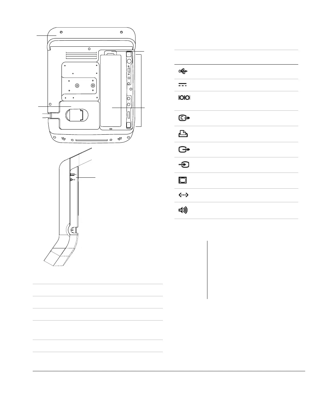
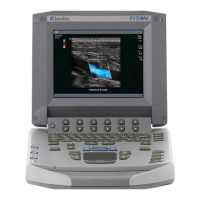
Figure 1 System Back (Top) and Side (Bottom)
Eachconnectoronthebackandsideofthesystem
hasasymbolthatdescribesitsuse.
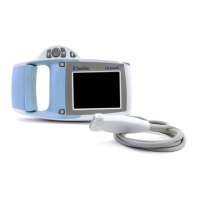
Installing or removing the battery
1Handle
2Transducer
3 Locking lever for battery
4 Connectors (See the table “Connectivity
Symbols on System.”)
5Battery
Connectivity Symbols on System
Symbol Definition
USB
DC input
RS-232 (DVD recorder or bar code
scanner)
Composite video out
Print control
S-video out
S-video in
DVI video out
Ethernet
Audio out
WARNING:
To avoid injury to the operator and
to prevent damage to the
ultrasound system, inspect the
battery for leaks prior to installing.
To avoid data loss and to conduct a
safe system shutdown, always keep
a battery in the system.