Manual Integrator Supercal 531 06-06-2011 14
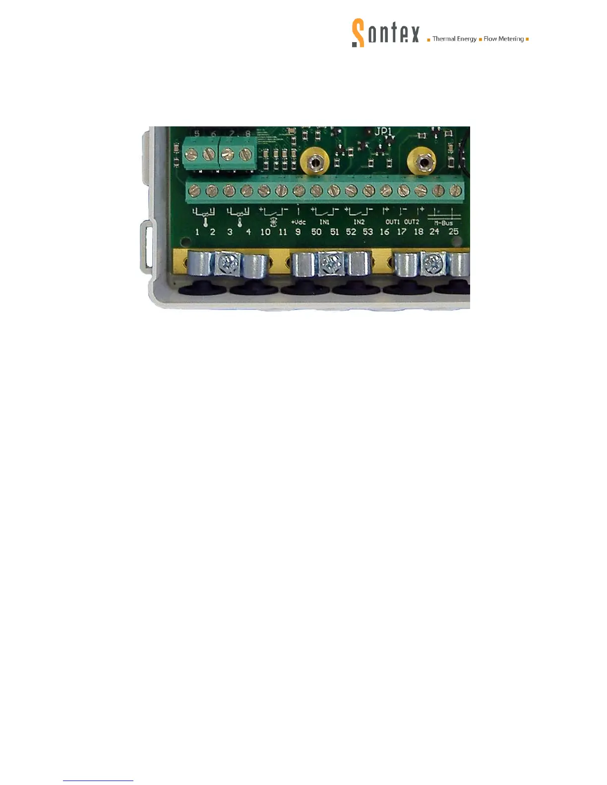
3.2 Wiring diagram
The integrator upper part has to be removed to connect the inputs and outputs. The wiring has to
be done as follows:
Terminal Description
1, 2 2-wire technology, temperature high
1, 2 and 5, 6 4-wire technology, temperature high
3, 4 2-wire technology, temperature low
3, 4 and 7, 8 4-wire technology, temperature low
10 (+) pulse input flow sensor
11 (-) pulse input flow sensor
9 power supply for flow sensor
50 (+) pulse input additional pulse input 1
51 (-) pulse input additional pulse input 1
52 (+) pulse input additional pulse input 2
53 (-) pulse input additional pulse input 2
16 (+) open-collector output 1
17 (-) open-collector outputs 1 + 2
18 (+) open-collector output 2
24 M-Bus (for M-bus module mounted at the factory) *
25 M-Bus (for M-Bus module mounted at the factory) *
*Terminals 24 and 25 are only active with mounted M-bus module (mounting at manufacturer).
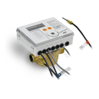
3.3 Flow measurement
Type-approved flow sensors with a pulse or frequency output can be connected to the integrator
Supercal 531.
The integrator has the following input pulse factors:
Up to 99'999’999 pulses/litre
Up to 99'999’999 litre/pulse