Manual Integrator Supercal 531 06-06-2011 25
6. The Communication Concept
For instructions on the installation and the parameterisation of the modules, we refer to „Start-up
and Applications“ (point 8), as from page 50
The terminal lay-out can be taken from the „wiring diagram Supercal 531“ (point 3.2.), page 15.
The specifications of the below mentioned communication configurations are stated in „Technical
Data “ (point 11.), as from page 66.
6.1 Standard configuration
By default, the Supercal 531 features an optical interface, a pulse input (terminal 10 and 11), two
additional pulse inputs (A1 and A2) and two open-collector outputs (B1 and B2).
On request, a M-bus or radio module can also be integrated in the standard configuration at the
factory.
6.1.1 Optical interface
The optical interface has been designed acc. to EN 61107 with the M-Bus protocol acc. to EN
1434. Its mechanical and electrical design corresponds to the ZVEI-Standard IEC 1107. This inter-
face allows the following start-up and service jobs via the communication protocol acc. to EN
60870-5:
Parameterisation of the optional communication modules
Parameterisation and read out of the current and recorded values.
Checking of the values
Test acc. to NOWA / UNICON-standard (NOWA: standardized heat meter adapter)
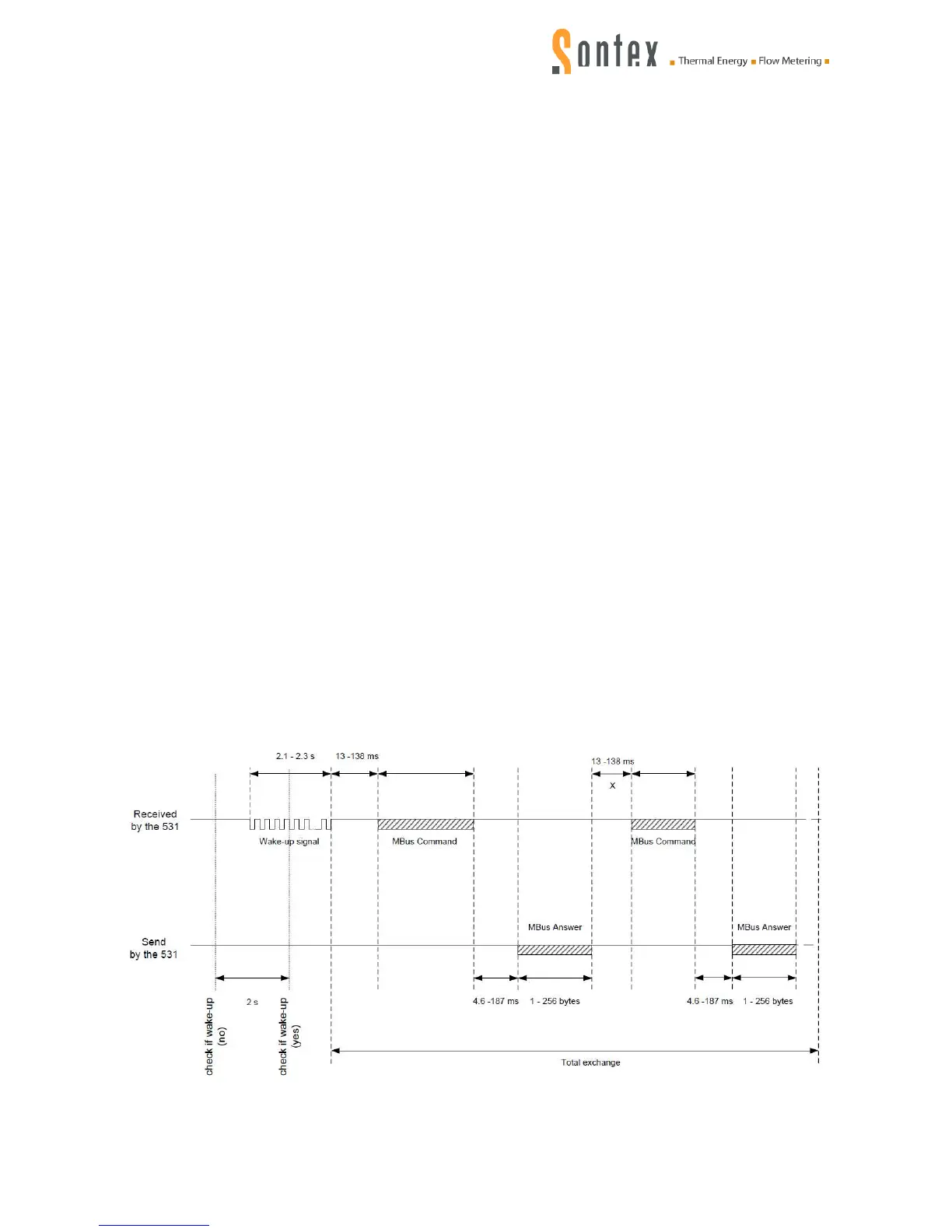
6.1.1.1 Timing of the optical interface
Every 2 seconds the integrator Supercal 531 checks if an wake up is pending.