Manual Integrator Supercal 531 06-06-2011 64
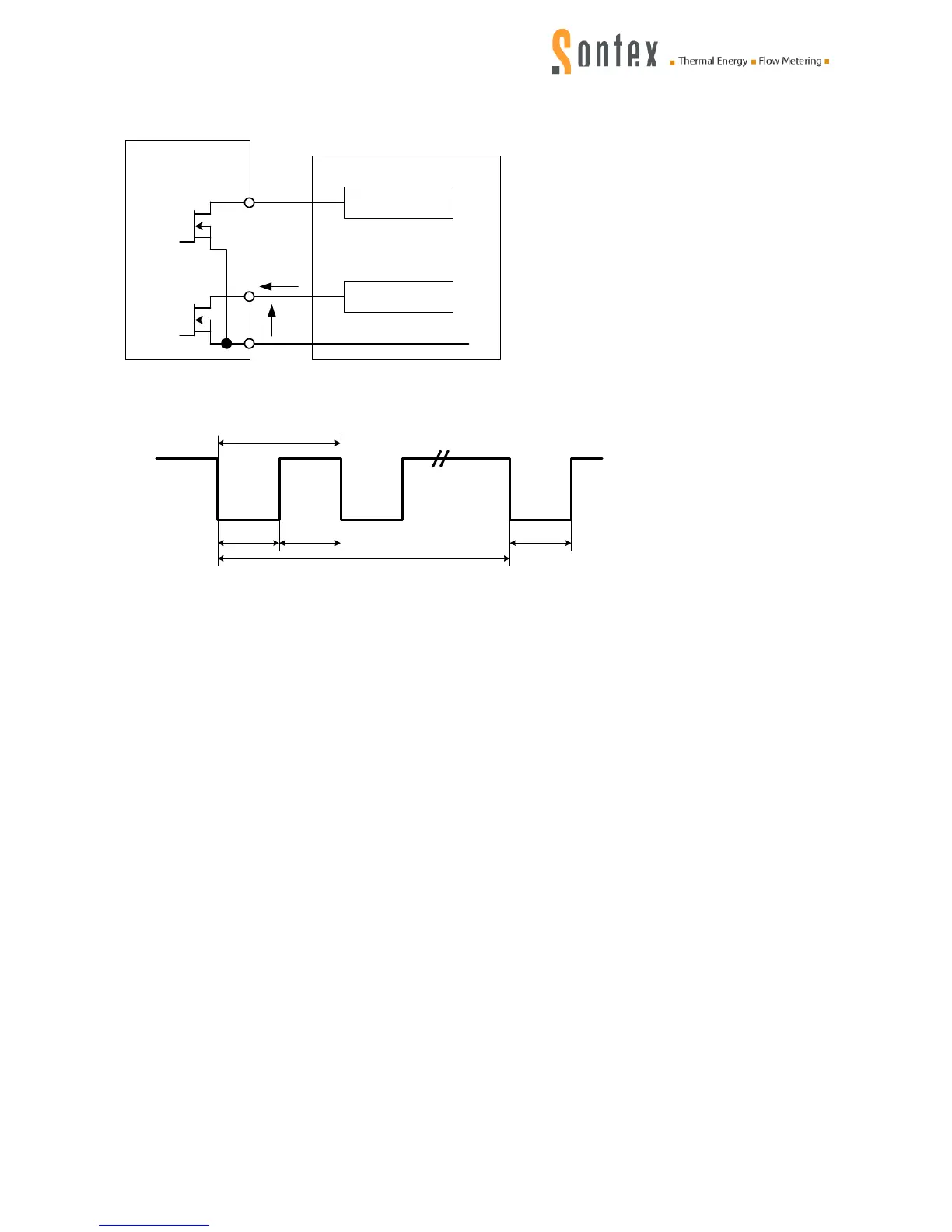
Circuit diagram:
Control of outputs
Ausgänge
531
Vout
Iout
Zusatzzähler
0V
Zähler 2
Zähler 1
16
18
17
Control of pulse
1 / f
t1
t2
U+
0V
Ruhend
Aktiv
t1
tm
Normal mode: t1 = t2 100 ms (pulse duty factor = 50%)
Fast mode: t1 = t2 0.04ms (pulse duty factor = 50%)
Vout max. < 30 V quiescent, 0.3 V active
Vout min. 2.0 V quiescent, 0V active
Iout max. < 5 µA quiescent at 30 V, < 100 µA active
Iout min. 0 µA quiescent, 1.65 µA active at 3,6 V
11.3.2 Options of standard setting
M-Bus module (factory-assembled)
Definition of interfaces acc. to EN 1434-3
Interface potential-free, protected against reverse polarity
Transmission rate 300...9’600 baud (… 4800 Baud on battery!)
Modify with SW Prog531
Data structure variable
Supply voltage:
UMU,M(MARK) 36 V
UMU,S (SPACE) 24 V
UM,M (SPACE) 12 V
UM,S (MARK) 11,3 V
Supply current:
IM 1,5 mA
IS 20 mA