A-12 Appendixes
Appendixes
Note
The example above shows the factory
default configuration.
You can use setup menu item 005 to
display a different type of time data in
the second line as well.
For details, see page 6-3.
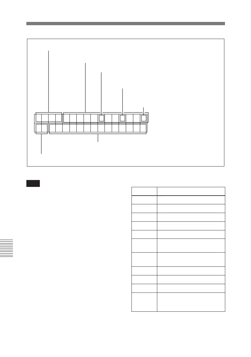
1 Time data type
2 Timecode reader drop-frame mark (525 mode)
3 Timecode generator drop-frame mark
(525 mode)
4 VITC data field mark
5 Recorder/player selection
6 Operating mode
Time data
1 Time data type
Display Meaning
CTL CTL counter data
TCR LTC reader timecode data
UBR LTC reader user bits data
TCR. VITC reader timecode data
UBR. VITC reader user bits data
TCG Timecode generator timecode
data
UBG Timecode generator user bits
data
IN IN point time data
OUT OUT point time data
AI AUDIO IN point time data
DUR The duration between any two
of the three edit points (IN,
OUT, AUDIO IN)
TCR . 23 : 5 9 . 40 . 18*
PSHUTTLESTILL
Information Displayed on the LCD Monitor