70
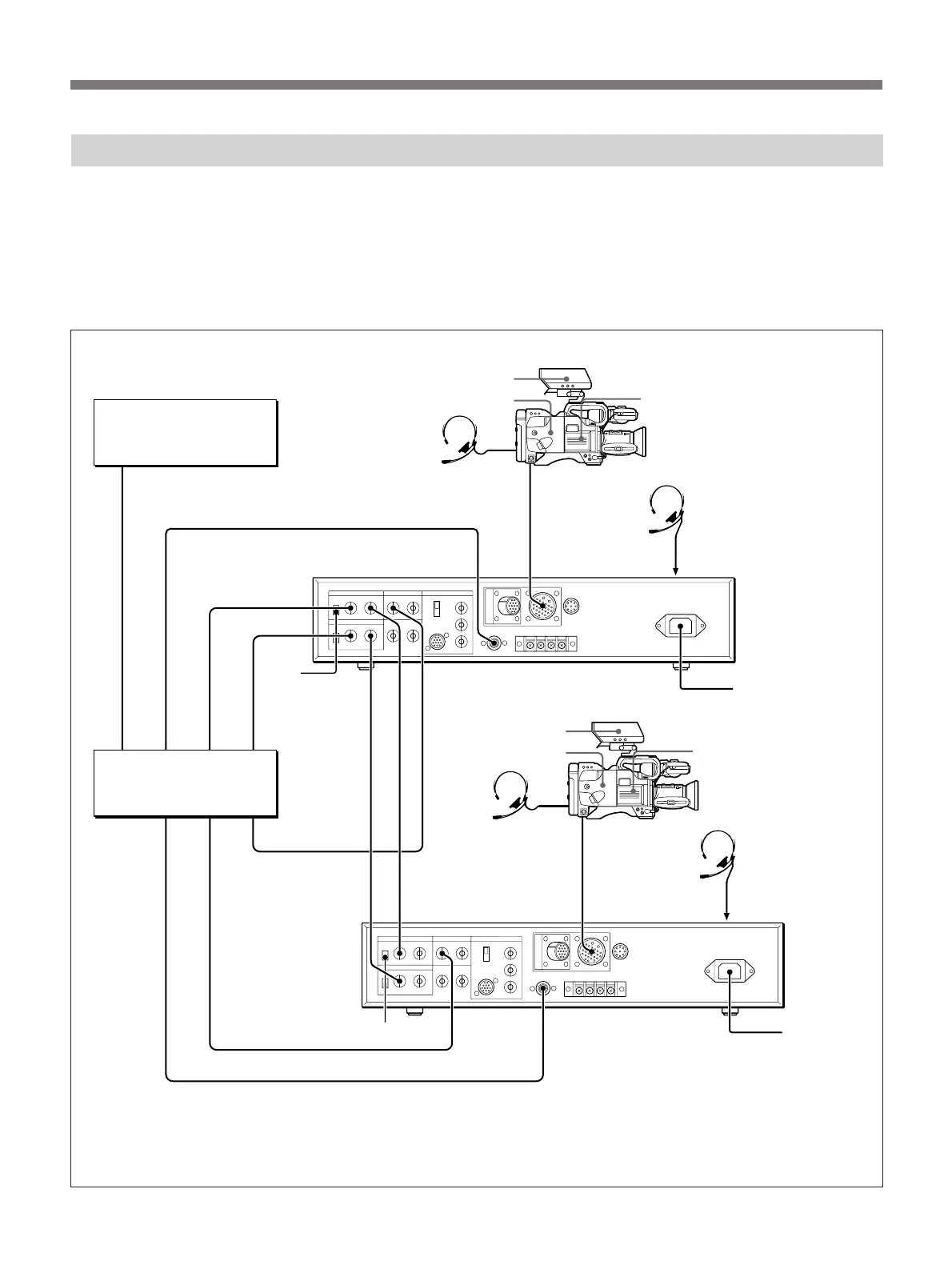
When using a number of cameras in the studio, it may
be necessary to use a CCU-M5/M5P/M7/M7P Camera
Control Unit to provide video and color sync between
cameras, and special effects and other devices to allow
switching, wipes and so forth.
DXF-40B/40BCE or DXF-50B/50BCE
CA-537/537P
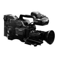
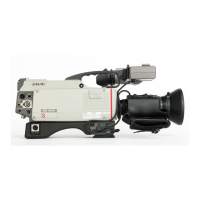
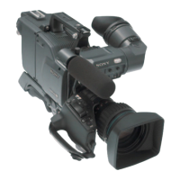
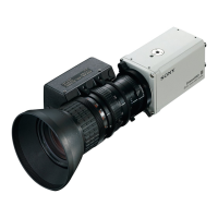
DXC-327B/327BP
DXF-40B/40BCE or
DXF-50B/50BCE
CA-537/537P
TALLY/INTERCOM CAMERA INTERCOM (on the front)
GEN LOCK IN RETURN VIDEO IN CAMERA INTERCOM (on the front)
VBS OUT TALLY/INTERCOM
RETURN VIDEO
GEN LOCK IN
to AC power supply
to AC power
supply
Headset
VIDEO IN
TALLY/INTERCOM
VIDEO IN
PGM OUT
TALLY/INTERCOM
PGM OUT
VBS OUT1
GEN LOCK OUT
RETURN VIDEO OUT
VIDEO OUT
Cables used
1 Power cord (supplied)
2 CCZ-A Camera Cable
3 BNC cable
4 DIN 4-pin cable
1
1
2
2
3
33
3 3
43
3
4
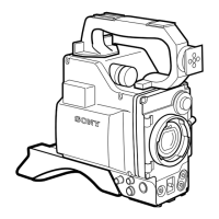
In the studio it may also be convenient to use a DXF-
40B/40BCE/50B/B0BCE Viewfinder.
The figure below shows an example studio
configuration.
For details, consult your sales repsresentative or supplier.
Connecting a Number of Cameras (Using a Camera Control Unit)
Advanced Operations
VTR
Switcher,
special-effects
generator
CCU-M5/M5P
camera control unit
DXC-327B/327BP
VIDEO IN
75-ohm
termination
switch to OFF
75-ohm termination switch to ON
CCU-M5/M5P
camera control unit
INTERCOM
Headset
INTERCOM
Hheadset
Hheadset


 To Next Page