45
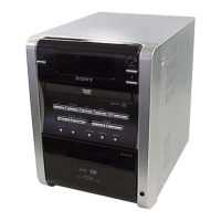
HCD-DV2D
• IC Pin Function Description
MAIN BOARD IC501 µPD78007 (SYSTEM CONTROLLER)
Pin No. Pin Name I/O Description
1RMUT O Tuner muting signal output
2 PMUT O Tape PLAY muting signal output
3 RPHD O REC/PLAY control signal output
4BIAS O BIAS ON/OFF control signal output
5 TSOL O Tape solenoid control signal output
6TMOT O Tape motor control signal output
7 TCNT O Tape control signal output
8 SMUTE I Not used Fixed at “L” in this set.
9 GND — Ground terminal
10 VDD — Power supply terminal (+5V)
11 STE I Stereo signal input
12 TUCE O Chip enable signal output to the tuner
13 TUND I Tuning signal input from the tuner
14 TOP O DVD/CD tray open control signal output
15 VEDA O Chip select output to the FL driver
16 VFCK O Clock output to the FL driver
17 VFSTB O Data output to the FL driver
18 TUDI O Data output to the tuner
19 TUDO I Data input from the tuner
20 TUCK O Clock output to the tuner
21 RDDA O Strobe signal input to the tuner
22 VUP I Volume up input
23 FPON O FL power supply control signal output
24 VDDI — Power supply terminal (+5V)
25 GND — Ground terminal
26 KEY1 I Function key input
27 KEY2 I Function key input
28 KEY3 I Function key input
29 SFTY I AC cut detect signal input
30 HDPN I Tape SW (PACK, HDPLY) signal input
31 REPT I Tape SW (RECF, RECR) signal input
32 VER I Not used Fixed at “L” in this set.
33 VDWN I Volume down input
34 AVR — Reference voltage terminal
35 TCL O DVD/CD tray close control signal output
36 RST I System reset signal input
37 XT2 I Subclock input (32.768KHz)
38 XT1 O Subclock output (32.768KHz)
39 IC — Not used
40 X2 I Main system clock input (8.38MHz)
41 X1 O Main system clock output (8.38MHz)
42 GND — Ground terminal
43 SHFT — Not used Fixed at “L” in this set.
44 INH I Power down detect signal input
45 REM I SIRCS signal input from the remote control reciever
46 RDCK O RDCK signal output to the tuner
47 MRST I MPEG flash memory reset signal input