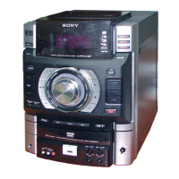
HCD-GN1300D
16
SECTION 3
TEST MODE
[GC TEST MODE]
• This mode is used to check the fl uorescent indicator tube,
LEDs, keys, VOLUME jog, OPERATION DIAL jog, model,
destination and software version.
Procedure:
1. Press [x] button, [ENTER] button and [DISC 2] button simul-
taneously.
2. All LEDs and segments in fl uorescent indicator tube are light-
ed up. All LEDs are lighted up in blue color except for [
]
LED where the LED is lighted up in red and blue color, [SUB-
WOOFER ON/OFF] LED in green color and METER BACK-
LIGHT LED and POWER LED in red color.
3. When you want to enter to the software version display mode,
press [DISC 1] button. The model and destination information
appears on the fl uorescent indicator tube.
4. Each time [DISC 1] button is pressed, the display changes to
display software version and date of the software creation. The
sequence is model destination, SC, GC, SYS, DVD, ST, TC,
TA, TM and MTR in this order, and returns to the model desti-
nation display.
5. Press [DISC 2] button, the key check mode is activated.
6. In the key check mode, the fl uorescent indicator tube displays
“K 0 J0 V0”.
Turn the [OPERATIONAL DIAL] clockwise; ”J” value in-
creases by one. Turn the [OPERATIONAL DIAL] counter-
clockwise; “J” value decreases by one. Each time a button is
pressed, “K” value increases. Press other keys on main unit
to check whether the key is detected. However, once a button
has been pressed, it is no longer taken into account. “V” value
increases in the manner of 0,1, 2, 3 ... if [VOLUME] knob is
turned clockwise, or it decreases in the manner of 0, 9, 8,7 ...
if [VOLUME] knob is turned counterclockwise.
7. When [DISC SKIP/EX-CHANGE] button is pressed after all
LEDs and segments in fl uorescent indicator tube light up, al-
ternate segments in fl uorescent indicator tube and LED would
light up. If you press [DISC SKIP/EX-CHANGE] button again,
another half of alternate segments in fl uorescent indicator tube
and LED would light up. Press [DISC SKIP/EX-CHANGE]
button would cause all segments in fl uorescent indicator tube
and LED turns off. Press [DISC SKIP/EX-CHANGE] button
again would cause all segments and LED lights up.
8. When [DISC SKIP/ EX-CHANGE] button is pressed after all
LEDs and segments in fl uorescent indicator tube light up, al-
ternate segments in fl uorescent indicator tube and LED would
light up. If you press [DISC SKIP/ EX-CHANGE] button
again, another half of alternate segments in fl uorescent indi-
cator tube and LED would light up. Press [DISC SKIP/ EX-
CHANGE] button again would cause all segments lights up.
9. To release from this mode, press three buttons in the same
manner as step 1, or disconnect the power cord.
[MC TEST MODE]
• This mode is used to check operations of the respective sec-
tions of Amplifi er and Tape.
Procedure:
• To enter MC Test Mode
1. Press [x] button, [ENTER] button and [DISC 3] button simul-
taneously.
2. The disc number indicators fl ash on the fl uorescent indicator
tube. The function is changed to VIDEO.
* Check of Amplifi er
1. Press [EQ BAND/MEMORY] button repeatedly until a mes-
sage “GEQ MAX” appears on the fl uorescent indicator tube.
GEQ increases to its maximum.
2. Press [EQ BAND/MEMORY] button repeatedly until a mes-
sage “GEQ MIN” appears on the fl uorescent indicator tube.
GEQ decreases to its minimum.
3. Press [EQ BAND/MEMORY] button repeatedly until a mes-
sage “GEQ FLAT” appears on the fl uorescent indicator tube.
GEQ is set to fl at.
4. When the [VOLUME] knob is turned clockwise even slightly,
the sound volume increases to its maximum and a message
“VOLUME MAX” appears on the fl uorescent indicator tube.
5. When the [VOLUME] knob is turned counterclockwise even
slightly, the sound volume decreases to its minimum and a
message “VOLUME MIN” appears on the fl uorescent indica-
tor tube.
* Tape function
1. Inserted a tape in deck. The function is changed to VIDEO
automatically when the recording is started by pressing [REC
TO TAPE] then press [ENTER] button. During recording the
ALC (Automatic Logic Control) is turned on.
2. During recording, press [m] will stop the recording and re-
wind the tape in Deck until the recording start position and the
function is changed to TAPE and playback of the tape in Deck
is started.
* To release from Common Test mode
1. To release from this mode, press [POWER] button.
2. The cold reset is enforced at the same time.
[COLD RESET]
• The cold reset clears all data including preset data stored in the
RAM to initial conditions. Execute this mode when returning
the set to the customer.
Procedure:
1 Press [x] button, [ENTER] button, and [POWER] button si-
multaneously.
2. The fl
uorescent indicator tube becomes blank for a while, and
the set is reset.
[VACS ON/OFF]
• This mode is used to switch ON and OFF the VACS (Variable
Attenuation Control System).
Procedure:
1. Press [POWER] button to turn the set ON.
2. Press [x] button and [OPTIONS] button simultaneously. The
message “VACS OFF” or “VACS ON” appears on the fl uores-
cent indicator tube.
[VACS DISPLAY]
• This mode is used to check the VACS level.
Procedure:
1. Press [POWER] button to turn the set ON.
2. Press [x] button, [SOUND FLASH] button and [DISC SKIP/
EX-CHANGE] button simultaneously.
3. The VACS Level Display, the fl uorescent indicator tube dis-
plays “VATB F APC”. “V” represent VACS , A represent
VACS level which is triggered by signal level, “T” represent
Thermal VACS NEO, B represent VACS level which is trig-
gered by temperature, “F” represent FAN is triggered by soft-
ware to turn in to high speed, “AP” represent APVACS (Abuse
Protection VACS) and “C” represent APVACS level which is
triggered.